Affordable & User-Friendly Three-Electrode Potentiostats for Educational Labs
Dr. Harnett's lab seeks cost-effective potentiostats under $100 each for students, based on experiment needs and hardware requirements. Upgrade and test existing designs for optimal performance.

Affordable & User-Friendly Three-Electrode Potentiostats for Educational Labs
E N D
Presentation Transcript
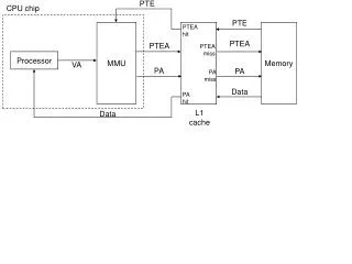
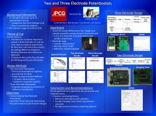
Two and Three Electrode Potentiostats Three-Electrode Design Sponsored By • Background Information • Dr. Harnett’s lab needs up to 15 potentiostats that are: • Inexpensive (less than $100 per unit) • Easy to assemble by students • OTS solutions range from $5K to $10K • Theory of Use • A potentiostat is: • The electronic hardware required to control a three electrode cell and run most electro-analytical experiments • An electronic instrument that controls the voltage difference between a Working Electrode and a Reference Electrode. • It measures the current flow between the Working and Counter Electrodes. • Design Methods • Two-Electrode Potentiostat • Previously developed by Capstone group during Fall 2010 • Follow-on project by Ben Williams • Firmware improvements • Hardware component revision • Three-Electrode Potentiostat • Originally developed by University of California Santa Barbara Cindy Harnett Group Members: Kyle Bloomer, Luke Bennett, Josh Geiman • Experiment • Tested the current difference in four orange juice samples caused by varying amounts of ascorbic acid • 0, 0.1, 0.2, and 0.3M of ascorbic acid in each sample, respectively • Electrode usage • Counter: Platinum wire • Working: Pencil “lead” • Reference: Standard Ag/AgCl DDMS Processor Board Two-Electrode Results Three-Electrode Results Expected Results Two-Electrode Design Arduino Development Board Daughter Card • Conclusions and Recommendations • Results gathered from experiment do not coincide with expected results. • Possible contributing factors: • Reference electrode in poor condition • Possible firmware issues with measurement execution • Possible errors in chemistry related procedures DDMS • Objectives • Improve existing Two-Electrode Potentiostat • Implement Three-Electrode Potentiostat • Test and compare results between designs