Download
1 / 31
320 likes | 641 Views
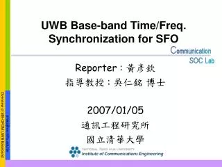
UWB Base-band Time/Freq. Synchronization for SFO. Reporter : 黃彥欽 指導教授 : 吳仁銘 博士 2007/01/05 通訊工程研究所 國立清華大學. Outline. MB-OFDM UWB Introduction Tx / Rx Block Diagram Synchronization of SFO Time-domain effect SFO analysis Freq-domain effect Simulation Result Future Work.

E N D
UWB Base-band Time/Freq.Synchronization for SFO Reporter : 黃彥欽 指導教授 : 吳仁銘 博士 2007/01/05 通訊工程研究所 國立清華大學
Outline • MB-OFDM UWB Introduction • Tx / Rx Block Diagram • Synchronization of SFO • Time-domain effect • SFO analysis • Freq-domain effect • Simulation Result • Future Work
MB-OFDM UWB • Spectrum: • 14 sub-bands • 5 band groups
System Parameters (The version 4/2005 post at MBOA web page)
MB-OFDM UWB Tx Generate Training Symbol P Data Source Signal Mapping D+P Inter-leaver Channel encoder Add 128-point IFFT Guard Tone Insert Preamble Insert Guard Interval PAPR Clipping Pulse Shaping PA DAC Time-Freq Code
MB-OFDM UWB Rx Coarse carrier phase Estimation Coarse carrier phase compensation ADC Packet Detection Symbol Timing Estimation + Freq. Hopping Signal Symbol Window Control Remove Guard Interval LPF LNA s/p Phase Offset Estimation Pilot Tracking Estimation P N P Sampling Clock Sync N-point FFT D D Channel Decoder De- Inter- leaver Signal De- mapping Channel Equalization D P/S Decoded Information Bits N Channel Estimation
DAC ADC channel T 2T 3T 4T T’ 2T’ 3T’ Sampling Freq. Offset (SFO) • SFO is caused by sampling instant mismatch between DAC and ADC.
SFO Effects Simulation (Time Domain)
Sampling Freq. Offset (SFO) (cont.) • Effect in Time Domain OFDM Symbol Window Drift FFT window This leads to irreducible ISI ! Need to add/drop 1 sample after every 151 OFDM symbols !
Coarse CFO Estimator Packet Detection CFO Correction Remove CP FFT Symbol Timing Estimator Data Preamble Residual Carrier Freq. Offset (RCFO) • RCFO is caused by non-exact carrier freq. offset (CFO) correction before FFT.
Sampling Freq. Offset (SFO) (cont.) • Effect in Freq. Domain Sub-carrier Symbol Rotation Phase Rotation pilot The rotated phase is the function of time and different between sub-carriers ! So the receiver has to track and compensate SFO and RCFO continuously in time !
SFO Effects Simulation (Frequency Domain) • Timing offset in time domain resulting in phase rotation in the freq domain
General Method • Use Pilots to estimate SFO • Symmetrically distributed around middle subcarrier • Use the knowledge of the linear relationship between phase rotation of negative (C1) and positive (C2) set. • Received pilot subcarriers • Calculate the rotation of the pilot from this symbol to the previous
General Method (cont) • Take the cumulative phase of for the two sets C1 and C2 • SFO estimation is given by
Our Proposed Method • Estimation Method • We use Least-Square (LS) algorithm to estimate the SFO and RCFO
LS estimation • No probabilistic assumptions about data, only a signal model is assumed • Data Model: • Least Squares error Model inaccuracies Noise x[n] Signal model Perturbation s[n] θ x[n] Error=ε[n] Signal model Σ s[n] θ
LS estimation (cont) • LS error criterion • The value of θthat minimizes J(θ) is the LSE. • If the signal s is linear, we can use matrix notation:
LS estimation (cont) • To find the minimum LS error, setting the gradient • equal to error :
Proposed Method (cont.) Enhance the BER performance by Using LS algorithm !
Simulation of using LS algorithm to estimate the slope and intercept
Add/Drop SFO Compensation 2 Sampling Frequency Offset Recovery • Digital approach in Baseband FFT Channel Equalizer ADC Pilot extraction SFO estimator l : symbol index k : subcarrier index
Future Work • Continue completing all the simulation • Make sure the sync. part will work successfully : • Combine with other parts in Rx-end • Consider the multi-path effect • Chip implementation: • Design the micro-architecture and write RTL code • Verify the system by FPGA board • Tapeout