Download
1 / 34
340 likes | 519 Views
Target system for hadron & neutrino beam lines at J-PARC. Y.Yamada (KEK-IPNS) for Nuclear/Particle physics group at J-PARC (Hadron beam-line SG, Neutrino beam-line SG, Target/Monitor SG) High-power Targetry for Future Accelerators September 8, 2003 . Contents Introduction of J-PARC

E N D
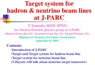
Target system for hadron & neutrino beam lines at J-PARC Y.Yamada (KEK-IPNS) for Nuclear/Particle physics group at J-PARC (Hadron beam-line SG, Neutrino beam-line SG, Target/Monitor SG) High-power Targetry for Future Accelerators September 8, 2003 • Contents • Introduction of J-PARC • Target and Target system for hadron beam line • Target system for neutrino beam line • (Y.Hayato will talk about neutrino target tomorrow)
J-PARC Tokai Tsukuba J-PARC:JapanProtonAcceleratorResearchComplex Nuclear/Particle physics experiment (first 2 years : phase1-) 3GeV PS Hadron beam line Normal conducting 400MeV Linac (170MeV at phase 1-) Neutrino beam line 50GeV PS To SuperKamiokande Phase 1:Approved in 2001, will be completed by 2007 Neutrino will be approved for FY2004-8(?)
Site View of the Project Facility for Nuclear/Particle Physics experiment (~2007) Facility for Neutrino Experiment (2004?~2008?) Life & Material Science (Neutron, Muon, RI) (~2007) Nuclear Transmutation 3 GeV PS (~2006) 50 GeV PS (~2007) 180 MeV Linac (~2006)
Machine power Design 10000 ESS Construction PSI Operation SNS 1000 3 GeV PS @J-PARC ISIS 100 TRIUMF Intensity (μA) IPNS 10 AGS KEK-500MeV FNAL-MI Booster CERN-PS 1 SPS 1 MW KEK- 12 GeV PS U70 0.1 Tevatron 0.1 MW 0.01 0.1 1 10 100 1000 10000 Energy (GeV) 50 GeV PS @J-PARC • Beam Energy: 50GeV (40GeV in Phase1-) • Beam Intensity: 3.3x10¹⁴ppp, 15μA (2x10¹⁴ppp, 9μA in Phase1-) (18x1014ppp, 80μA in future) • Beam Power: 0.75MW (0.36MW at Phase1-) (4MW in future)
Acceleration/extraction cycle 3.53 s Slow extraction to hadron beam line: 0.70s Energy Acceleration:1.96s Deceleration: 1.90s Current down:0.70s Fast extraction to neutrino beam line nothing:0.70s Injection:0.17s (Sec.)
Hadron beam line • Slow extraction beam line • Physics with high intensity secondary K beam • Strangeness Nuclear physics • Rare K decay Production target:T1 50GeV PS Extraction point dump NP-Hall Switch Yard (SY) ~200m
Target and secondary beam lines • Production target : T1 • Rotating Nickel disks • thickness: ~54 mm • radius: ~24 cm • cooled by water • developed by Y.Yamanoi • et. al. HR K1.8 K0 K1.1 Proton beam NP-Hall
Design of T1 30% interaction Ni target • 1.3x10²¹ protons/year on Target (4000 hours/year) • Radiation shielding • Max. yield of secondary beam • Temperature rise • Point source for secondary beam
Water cooling of T1 • Rotating Ni disks • Diameter : 48cm, Thickness : 54 mm (9mm-t6disks) • 1 rotation per 0.7s (slow extraction period) : 85 RPM • Partially cooled by water 48cm x 54mmt • ANSYS: • After 0.7s exposure • 1200 W/m2K assumed beam Highest ~94ºC 24cm x 54mmt 85RPM Lowest ~40ºC Highest ~196ºC Lowest ~136ºC Cooling water
Gas cooling of T1 48cm x 54mmt 48cm x 54mmt Natural convection 10 W/m2K assumed Highest ~ 602ºC: too high Lowest ~ 409ºC Forced convection 100 W/m2K assumed Highest ~ 148ºC: still high Lowest ~ 40ºC
R&D for T1 • Items • Optimization of diameter, thickness, # of disks(gaps) • Rotation speed, Method of rotation • Durability • Container & shielding • Cooling system • Beam window & vacuum sealing • Maintenance method Nickel disks (24cm x 6mmt x 9, 24kg) Beam • • Prototypes • Mockup
Water velocity at T1(1) • Relative velocity between disk and water • affects on heat transfer coefficient • measured by PIV(Particle Image Velocimetry) One Ni and two acrylic disks CCD Camera YAG Laser
Water velocity at T1(2) • Results: • Typ. velocity ~ 1 m/s @85RPM • Gap between disks • should be > 2mm • RPM should be < 150RPM • Fluid simulation • Reproduce relative velocity • Estimate heat transfer coefficient • Parameter survey on • Number of disks (gaps) • Gap length • Rotation speed • Depth in water • etc Measured relative velocity between disk and water (cm/s)
Container of T1 Target support Moving system Target off Alignment pins Ni target disk 48cm 5.4cm-t Water pipe Bearing Beam Cooling water Alignment pins
Cooling system of T1 Service space Filter In:32ºC 2.4m3/h Heat exchanger Pump Out:37ºC beam target Under test with Mockup Water tank:0.08m3 • Radioactivity of water after 30 days operation: ~24 kBq/cm3 • Thinned into 15 Bq/cm3 and thrown away • (Thinned into 1.2 kBq/cm3 and moved by tank track)
Mockup around T1 motor container East counter hall at KEK
Beam window for T1 T1 container • Double wall (SS and Al) • cooled by He flow • gap: ~1cm • remote maintenance He Air T1 target Vacuum chamber ~10-3Torr Al SS SS Al Beam axis Primary beam line:~10-3Torr He 1kg/cm2 1m/s T1downstream windows diameter:30cm T1 upstream windows diameter:10cm Water
T1 downstream window • Diameter: ~30cm • Vacuum side: Aluminum • Air(T1) side: SS • 0.1mm-t at center • 5mm-t at edge (water cooled) • Temperature rise of SS window at center • +170ºC (forced convection by He flow(~1m/s) : 100W/m2K) • +810ºC (natural convection : 10W/m2K)
Shield around T1 ~18m Concrete shield block ~10m Service space: 2m(W)1m(H) Water pump Iron shield 2m T1 container Concrete shield Beam The whole system will be tested by the T1 mockup.
Target Area Large Vacuum Chamber (~3kW) K1.8 D1(7.2kW) Q1(<1kW) Iron block (1.4kW) 2m Beam Dump Cu collimator (55kW) T1 target(12kW) 2.9m KL K1.1 Cu collimator (76kW)
Residual dose around T1 Cooling pipe 0.15 mSv/h Dose by MARS One day cooling after 30-days operation Half year cooling after 1-year operation Service space 0.1 μSv/h Vacuum chamber SUS 3.2 Sv/h 1.2 Sv/h Ti 1.1 Sv/h 97 mSv/h Concrete 0.1 μSv/h Iron 22 μSv/h Iron 3.8 mSv/h Container 2.2 Sv/h 850 mSv/h Q1B 110 mSv/h 49 mSv/h beam Trench Collimator 710 mSv/h 420 mSv/h T1 650 Sv/h 230 Sv/h Base plate 560 mSv/h 210 mSv/h Vacuum flange 30 Sv/h 11 Sv/h Collimator 380 mSv/h 100 mSv/h K1.8D1 530 mSv/h 270 mSv/h K1.8Q1 62 mSv/h 33 mSv/h
Remote maintenance for T1 • Maintenance work • should be done at service space • Disconnect cables and • cooling tubes. • Detach vacuum flanges. • Replace shields with cask. • Detach shaft, disks and • upper plate, and • move them to stock space. • Install new parts with cask. • Replace cask with shields. • Connect cables and tubes. • requires remote maintenance tools motor water 3m shield beam target beam Front view Side view
Remote vacuum sealing • Design specification • Inner Diameter: 30cm • Metal sealing • Small leak:~110-10 Pa•m3/s • Remote operation • Operation time: 1~5 min. • Small force required • Candidate • Mechanical holding (V-block) • Pillow seal • Radial seal (under development) Prototype of “Radial seal” developed by Y.Yamanoi(KEK) , M.Tsuchiya(IHI Ltd) and Usui Kokusai Sangyou Kaisya Ltd.
Remote lifting Tools Crane Magnet Specification • Up to 40t • Short height • Remote connection • Video camera viewing • Two or four points lifting • Interlock for one-side lifting Under design Lifting tools from CERN and PSI
Neutrino beam line Fast-extracted proton beam line Decay volume Target station Beam dump 50GeV PS Super- Kamiokande νμ beam of ~1GeV • nm→ nx disappearance • nm→ neappearance
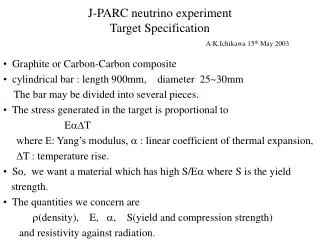
Neutrino target • Graphite rod • diameter:30mm, Length:900mm (80% interaction) • beam size: σr ~6mm • fixed inside 1st horn • 20kw heat load: cooled by water • Hayato’s talk tomorrow 3rd Horn 2nd Horn 1st Horn Target 0.75MW beam
Neutrino target station 33m 40t crane Ground level Concrete blocks Final focus Beam window Iron shield Decay volume Beam window Concrete Baffle Target & 1st horn 2nd horn 3rd horn 22m 11m Service pit Machine room Helium container Stock room for activated parts Iron shield
Radiation shield and dose Floor: <12.5 μSv/h Radiation dose in 0.75MW operation (by MARS) Concrete 4.5m Machine room Service pit Concrete 1m Iron 2.2m Outer surface of concrete : <5mSv/h Stock room for radioactive parts Concrete 3.6m Iron 1.5m Iron 1.5m Concrete 3.6m
Helium container • Reduce radioactivity in gas and corrosion by NOx • 3m(W)6m(H)15m(L), 20cm thick Aluminum • Filled by 1 kg/cm2 Helium gas (130m3) • Heat load ~170 kW: water cooled • Under conceptual design Final focus Beam window Decay volume Beam window Helium container Concrete Baffle Target & 1st horn 2nd horn 3rd horn
Residual dose Residual does: one (seven) day cooling after one year operation (by MARS) Machine room Floor of service pit ~0.007(0.004) μSv/h Service pit Upper iron shield Outer : 22(16) μSv/h Inner : 0.56(0.42) Sv/h Helium container (Aluminum) ~0.65(0.17) Sv/h
Stock room for activated parts • Stock broken and activated targets/horns etc (5~20 years?) • Use cask and move under ground level Wall: 20cm concrete Ground level Top view of Target station Concrete Iron Stock room
Control of air • Building (8300m3): • Ventilation through stack • Service pit(230m3) • Machine room(140m3) • Keep out in operation time • Operation time:circulation • Maintenance:ventilation • Helium container: • Keep out forever • Circulation of Helium • Stock room for radioactive parts • Keep out forever • Operation time:circulation • Maintenance:ventilation
Cooling and radioactivity • After 3 weeks of 0.75MW operation, • Target (heat load:20kW) : • 0.001m3 & 300kBq/cm3 • thinned into 20m3 of 15 Bq/cm3 and thrown away • Horns (heat load:~30kW) : • 0.6m3 & 5kBq/cm3 • 200m3 of 15 Bq/cm3 • Iron shields & Helium container (heat load~210kW) : • ~0.1m3, ~30kBq/cm3 • ~200m3 of 15 Bq/cm3
Summary • Target system for 0.75MW-50GeV beam at J-PARC • under design and R&D stage • and will be completed by 2007~2008 • Ni disks for hadron beam line • Carbon rod for neutrino beam line • Key points on target system • Radiation level and residual dose • Remote maintenance • Cooling • Cost, man power, schedule, etc.