Download
1 / 51
510 likes | 642 Views
FM Synchronous Boosters And Single Frequency Networks Tim Bealor, VP RF Products John Macdonald, Sales Manager, Europe Middle East, Africa Lutfi Aysan, Onair Medya. Today’s Topics. Company Overview Sample Installations & Technological Issues System Configurations BE Solutions.

E N D
FM Synchronous Boosters And Single Frequency Networks Tim Bealor, VP RF Products John Macdonald, Sales Manager, Europe Middle East, Africa Lutfi Aysan, Onair Medya
Today’s Topics Company Overview Sample Installations & Technological Issues System Configurations BE Solutions
Today’s Topics Company Overview Sample Installations & Technological Issues System Configurations BE Solutions
Corporate Overview Nearing fifty years of serving radio broadcasters worldwide Headquartered in Quincy, Illinois Products encompass program generation, audio and data management, inter-facility transport and analog and digital transmission
FM Transmitters • Comprehensive product line from 50W to 70KW • All transmitters upgradeable to HD Radio
AM Transmitters • Comprehensive product line from 500W to 100KW • All transmitters upgradeable to digital
Transport Products Marti • The ONLY answer for traditional RPU applications • Reliable, cost effective composite & discreet STL’s Digital Cellcast • Take your station anywhere! • The ultimate in remote portability Big Pipe LT • High bandwidth digital performance • Upgrade you link for HD compatibility at an affordable price Audio Over IP • No more worries about long, unreliable paths • Originate your signal with remote IP access from your laptop
Studio Products AudioVAULT • Broadcast delivery software system • Tools to manage, create and deliver content • Personalized workspaces The Radio Experience (TRE) • Complete message management capabilities • Supports RDS, RT+, HD, Web and more SoniXtream • Turnkey internet streaming services • Branded custom players • Ad insertion • Multiple revenue generation components
Today’s Topics Company Overview Sample Installations & Technological Issues System Configurations BE Solutions
Synchronous FM Boosters:Why do we need them? • Scenario #1 – Filling in dead spots in coverage. • Allows the broadcaster to fix areas that are terrain shielded but would otherwise be within the 1 mV/M (or other) contour. • Scenario #2 – Covering a long road with one station. • Increasingly, stations are getting licenses for a coverage along a major highway with just a single frequency. • Scenario #3 – Regional coverage. • Allows a licensee to cover a region with several stations – all on the same frequency
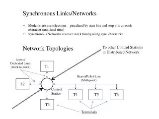
Fixing Dead Spots Dead spots are created by terrain shielding – where there is no reasonable line of site. A low power, on frequency booster may be located within the shadowed area to improve coverage. Interference Areas Main Transmitter Booster Transmitter
Main 25kW FM Transmitter Synchronous FM 250W Booster Tall Buildings – Central Business District Terrain Shielded Area
Creating continuous coverage on a road • Long, important highways are good targets for a radio station you can listen to without changing the dial. • Many small transmitters are synchronized to provide unbroken service.
Regional Coverage True, regional stations may be created by synchronizing high power stations. Station identity can be created – the frequency is the same across the whole region. Frequency allocation is easier – the same frequency can be used for adjacent stations.
The Problem: Interference Zones • Where the coverage areas overlap, and the ratios of the signal strengths approach unity, the signal quality is affected. Interference Zone Basel Zurich
Key Issues • Where the coverage areas overlap, and the ratios of the signal strengths approach unity, the signal quality is affected. • If the RF carriers are not frequency synchronized, significant distortion and noise will result. • If the audio levels are not exactly the same, the noise floor increases dramatically with a “white noise” which varies with the level of the audio. • If the pilots are not synchronized, in both frequency and phase, the pilot detector in the receiver will switch back and forth and this will be audible in the stereo signal. • If the audio phase is not synchronized, distortion results. • If everything – audio, pilot & carrier are all synchronized, the signal will be optimized.
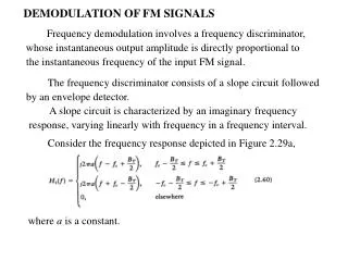
Composite Baseband: L=5kHz, R=7kHz 0dB -20dB -40dB -60dB -80dB -100dB 0 Hz 10 kHz 20 kHz 30 kHz 40 kHz 50 kHz
Two carriers – in phase 0dB -20dB -40dB -60dB -80dB -100dB 0 Hz 10 kHz 20 kHz 30 kHz 40 kHz 50 kHz
Two carriers – ¼ dB deviation difference 0dB -20dB -40dB -60dB -80dB -100dB 0 Hz 10 kHz 20 kHz 30 kHz 40 kHz 50 kHz
Two carriers – ½ dB deviation difference 0dB -20dB -40dB -60dB -80dB -100dB 0 Hz 10 kHz 20 kHz 30 kHz 40 kHz 50 kHz
Two carriers – 1 dB deviation difference 0dB -20dB -40dB -60dB -80dB -100dB 0 Hz 10 kHz 20 kHz 30 kHz 40 kHz 50 kHz
Two carriers – 90° time delay 0dB -20dB -40dB -60dB -80dB -100dB 0 Hz 10 kHz 20 kHz 30 kHz 40 kHz 50 kHz
Two carriers – 180° time delay 0dB -20dB -40dB -60dB -80dB -100dB 0 Hz 10 kHz 20 kHz 30 kHz 40 kHz 50 kHz
Today’s Topics Company Overview Sample Installations & Technological Issues System Configurations BE Solutions
Previous System Block Diagram May be accomplished with GPS receivers at both sites, or by use of a reference tone to sync both exciters. Problem: Doesn’t provide synchronized audio phase or level, or pilot phase.
What’s needed • (2) FXi-60 or FXi-250 Digital FM exciters • (1) Uncompressed Digital STL with AES/EBU input and output. We have used the Moseley Starlink 9400Q. • (2) Rack mounted GPS receivers with 10MHz TTL level output and outdoor antenna. We have used the ESE Model 110. • (1) AES/EBU Splitter/Delay with minimum delay time of approximately one microsecond, and increments of one microsecond to a maximum delay of one millisecond. We have used the Quantec Zombie 1212/DSP.
Today’s Topics Company Overview Sample Installations & Technological Issues System Configurations BE Solutions
BE’s approach - Synchronize everything • The entire system is digital. • The audio is synchronized by using an uncompressed Digital AES/EBU Link • The levels of the transmitted audio are locked because we use the AES/EBU inputs on the FXi ESP series exciter. • The carriers and the pilot are synchronized by using the internal GPS receiver. • The delays are extremely accurate because of 1usec internal delay accuracy • A patent has been applied for.
This is what makes it happen FXi 60/250esp Adaptive pre-correction Internal delay Internal GPS receiver IP connectivity Dual RF outputs Direct to carrier synthesis And Much Much More
No External GPS Required • Internal GPS Receiver with rear panel antenna connection • Self Contained Synchronous Booster Operation • Locked to GPS, 10MHz and 1PPS • Pilot and Carrier locked to 1PPS • 1usec delay resolution designed to specifically accommodate booster operation Timing Inputs
Ideal for Analog and HD Simulcast Only BE provides delay of composite input Delay AES Inputs 1usec delay resolution 0 to 15 seconds delay of FM Analog for Diversity Delay User defined Ramp Up and Ramp Down Time
0.1dB Deviation Accuracy If the modulation levels from two different exciters in a booster application are not exactly the same, it will result in the audio having a significant amount of noise and distortion. When implementing a synchronous or single frequency network the AES audio input should be used. This allows the FXi esp exciter to set the modulation levels to 0.1dB accuracy. Level differences of 0.3 to 0.5dB can result in poor audio quality near the overlap areas.
System Synchronization • Signal Outputs for external use • 10MHz • 1PPS • 19kHz Pilot • Internal GPS eliminates need for additional GPS receiver Timing Outputs
True Dual Exciter Operation • Dual RF Outputs allow one exciter to drive TWO transmitters! • High Power (0 to 250 watts) • Medium Power (0 to 15 watts) • Higher output power levels eliminate the need for additional external amplifiers High Power RF Output Medium Power RF Output
Rich in Audio Inputs… • More than any competing brand! • Audio Inputs • Dual Independent AES/EBU Inputs eliminate the need for external AES switching • L & R Analog Inputs • Balanced & Unbalanced Composite Inputs Balanced & Unbalanced Composite Inputs Dual Independent AES Inputs L&R Analog Inputs
..with Easy Source Setup • Primary/Backup Audio Source Setup • AES 1 • AES 2 • Composite • Analog L&R
Dynamic RDS Generator • Truly expands your RDS message capabilities! • Accepts dynamic serial RDS data or external generator • Eliminates need for external RDS generator • Serial data from source Dynamic RDS Input External RDS Generator Input
Flexible I/O Configuration • Allows flexible operational control for specialized installations • More than 45 unique settings • User-Defined General Purpose I/O • Can be used with any remote interface • 12 inputs with 12 outputs • All I/O’s are mode selectable Defined GPI/O User-Defined GPI/O
“True” Silence Sense Detection • No dead air in your revenue stream • User adjustable parameters-You’re in Control! • Threshold Level • Switchover Time • Switchback Time
Upgrades Station Measurement Capability • Instrument Grade Spectrum Analyzer eliminates the need for an external unit • Capable of measuring NRSC mask compliance • High resolution spectrum display of all modes • -20 dB ratio FM+HD • -10 dB ratio FM+HD • FM Only • HD Only
Ethernet Connectivity • IP Addressability for Remote Access • Easy set up
Reduced Downtime in Backup Operation • 8 Independent, selectable and downloadable configurations • Mode of Operation • Frequency • Output Power • Audio Source • N+1 Applications • Backup Transmitter Applications
Reduces AES Conversion Cost • Provides Composite output to drive main analog or backup transmitter • Eliminates the need to upgrade an analog only transmitter to accept AES input • Eliminates need for external stereo generator Composite Output
Efficient Operation and Troubleshooting • Front Panel Diagnostics and Metering • Larger Front Panel Display • 8.4” display • Soft-Key Menu Selection • 18 analog parameters • Forward Power • Reflected Power • Power Supply Voltages • Alarm Indication • Latched Output • Fault Indication • Non Latched • Event Logging
Lower Cost of Ownership Things you may NOT need with the FXi 60/250esp…. • Spectrum Analyzer • GPS Receiver • External Power Amplifiers • AES External Switching • External Stereo Generator • Standby Exciter • Backup Transmitter $ 6,000- $20,000 $ 1,300 $ 3,500 $ 800 $ 2,000 $ 5,000- $15,000 $ 15,000
Thank You Tim Bealor, tbealor@bdcast.com John Macdonald, jmacdona@bdcast.comwww.bdcast.com Lutfi Aysan, aysan@onair.com.tr