
0,15
Thermo Top Z/C; E / Thermo Top S. Connection to the vehicle fuel system. Fuel Supply. Diesel. Gasoline. l + l. . 7 m. l + l. . 4,5 m. 1. 2. 1. 2. l 1,2 m. . l 0,5 m. . 1. 1. l 5,8 m. . l 4 m. . 2. 2. with max. perm. overpressure

0,15
E N D
Presentation Transcript
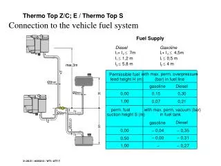
Thermo Top Z/C; E / Thermo Top S Connection to the vehicle fuel system Fuel Supply Diesel Gasoline l + l 7m l + l 4,5m 1 2 1 2 l 1,2 m l 0,5 m 1 1 l 5,8 m l 4 m 2 2 with max. perm. overpressure (bar) in fuel line Permissible fuel feed height H (m) gasoline Diesel 0,00 0,15 0,30 1,00 0,07 0,21 perm. fuel with max. perm. vacuum (bar) suction height S (m) in fuel tank Diesel gasoline 0,00 – 0,04 – 0,35 – 0,00 – 0,31 0,50 1,00 – – 0,27 31.08.01 / tt060213 / WTI / ATT-T
Thermo Top E / Thermo Top Z/C Installation example VW Bora TT-E/TT-Z/C 1 Heating unit Thermo Top Z/C or E 2 Flat fuse holder and fan relay 1 Seal, Formwasher 2 Stopnut 3 Hose 4 Wireclip 5 Clip 6 Clip 7 Clamptube, black 3 Digital timer 4 Exhaust silencer 5 Combustion air intake line 6 Metering pump 31.08.01 / tt060215 / WTI / ATT-T
Thermo Top Z/C; E Metering pump DP 2 DP 2 R 2 DP 2 DP 30 0-90° 0-90° 0-180° 0-180° 0-180° 0-180° 0-180° 0-180° horizontal only 31.08.01 / tt060212 / WTI / ATT-T
1 Thermo Top 3 2 4 Thermo Top Integration into fuel system of injection enginesIn-series integration into return line 1 Injection system 2 Engine 3 Return line 4 Flow line 31.08.01 / tt060101 / WTI / ATT-T
1 2 3 Thermo Top Thermo Top Integration into engine-water circuit, integration in secondary circuit (non-return valve) 1 Engine 2 Non-return valve 3 Vehicle heat exchanger 31.08.01 / tt040200 / WTI / ATT-T
1 2 Thermo Top Thermo Top Integration into engine/water circuit In-series integration 1 Engine 2 Vehicle heat exchanger 31.08.01 / tt040100 / WTI / ATT-T
1 Thermo Top 3 2 4 Thermo Top Integration into fuel system of injection enginesIn-series integration into return line 1 Injection system 2 Engine 3 Return line 4 Flow line 31.08.01 / tt060101 / WTI / ATT-T
Thermo Top Example of fan control, Audi A4 air conditioning system 1 Vehicle fuse holder 2 Fan motor 3 Recirculating air valve 31.08.01 / tt050900 / WTI / ATT-T
Thermo Top Z Wiring harness, upgrade kit 1 Digital timer 2 Connection f. supplementary heating device 3 'Equipment on' indicator 4 Circulating pump 5 Fan connection 6 Negative conductor 7 Relay base 8 Relay base 9 Fan relay 10 Negative conductor 11 Fuse block 12 Negative conductor 13 Mounting plate 14 Fuse cover 15 Voltage supply terminal 30 16 Werle relay 31.08.01 / tt050601 / WTI / ATT-T
Thermo Top Z Wiring harness, supplementary heating device Heater Metering pump Diagnostic connector Thermostat A B C D 31.08.01 / tt050501 / WTI / ATT-T