Networking
Networking. 1961: Kleinrock - queueing theory shows effectiveness of packet-switching 1964: Baran - packet-switching in military nets 1967: ARPAnet conceived by Advanced Research Projects Agency 1969: first ARPAnet node operational. 1972: ARPAnet demonstrated publicly

Networking
E N D
Presentation Transcript
1961: Kleinrock - queueing theory shows effectiveness of packet-switching 1964: Baran - packet-switching in military nets 1967: ARPAnet conceived by Advanced Research Projects Agency 1969: first ARPAnet node operational 1972: ARPAnet demonstrated publicly NCP (Network Control Protocol) first host-host protocol first e-mail program ARPAnet has 15 nodes Internet History 1961-1972: Early packet-switching principles
1970: ALOHAnet satellite network in Hawaii 1973: Metcalfe’s PhD thesis proposes Ethernet 1974: Cerf and Kahn - architecture for interconnecting networks late70’s: proprietary architectures: DECnet, SNA, XNA late 70’s: switching fixed length packets (ATM precursor) 1979: ARPAnet has 200 nodes Cerf and Kahn’s internetworking principles: minimalism, autonomy - no internal changes required to interconnect networks best effort service model stateless routers decentralized control define today’s Internet architecture Internet History 1972-1980: Internetworking, new and proprietary nets
1983: deployment of TCP/IP 1982: SMTP e-mail protocol defined 1983: DNS defined for name-to-IP-address translation 1985: FTP protocol defined 1988: TCP congestion control new national networks: Csnet, BITnet, NSFnet, Minitel 100,000 hosts connected to confederation of networks Internet History 1980-1990: new protocols, a proliferation of networks
Early 1990’s: ARPAnet decommissioned 1991: NSF lifts restrictions on commercial use of NSFnet (decommissioned, 1995) early 1990s: Web hypertext [Bush 1945, Nelson 1960’s] HTML, HTTP: Berners-Lee 1994: Mosaic, later Netscape late 1990’s: commercialization of the Web Late 1990’s – 2000’s: more killer apps: instant messaging, peer2peer file sharing (e.g., Naptser) network security to forefront est. 50 million host, 100 million+ users backbone links running at Gbps Internet History 1990, 2000’s: commercialization, the Web, new apps
Regional A Australia Japan NAP NAP NAP NAP Europe Backbone 2 Backbone 4, 5, N Regional B Backbone 1 Backbone 3 Structure of the Internet MAPS UUNET MAP KOREA SOURCE: CISCO SYSTEMS
Internet Host Count 1991-2003 “Host” computer than can be reached by a URL ESTIMATE: 300,000,000 hosts by 2005 172,000,000
Internet Leverage by Country WORLD TOTAL USERS (AUG. 2003): 700,000,000 LEVERAGE = % OF INTERNET USERS ÷ % OF WORLD POPULATION
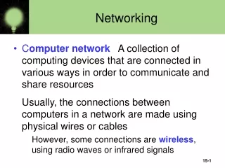
millions of connected computing devices: hosts, end-systems PCs workstations, servers PDAs phones, toasters running network apps communication links fiber, copper, radio, satellite transmission rate = bandwidth routers: forward packets (chunks of data) router workstation server mobile local ISP regional ISP company network What’s the Internet: “nuts and bolts” view
“Cool” internet appliances IP picture frame http://www.ceiva.com/ Web-enabled toaster+weather forecaster World’s smallest web server http://www-ccs.cs.umass.edu/~shri/iPic.html
protocolscontrol sending, receiving of msgs e.g., TCP, IP, HTTP, FTP, PPP Internet: “network of networks” loosely hierarchical public Internet versus private intranet Internet standards RFC: Request for comments IETF: Internet Engineering Task Force What’s the Internet: “nuts and bolts” view router workstation server mobile local ISP regional ISP company network
communication infrastructure enables distributed applications: Web, email, games, e-commerce, database., voting, file (MP3) sharing communication services provided to apps: connectionless connection-oriented What’s the Internet: a service view • cyberspace [Gibson]: “a consensual hallucination experienced daily by billions of operators, in every nation, ...."
human protocols: “what’s the time?” “I have a question” introductions … specific msgs sent … specific actions taken when msgs received, or other events network protocols: machines rather than humans all communication activity in Internet governed by protocols What’s a protocol? protocols define format, order of msgs sent and received among network entities, and actions taken on msg transmission, receipt
a human protocol and a computer network protocol: TCP connection response Get http://www.awl.com/kurose-ross Got the time? 2:00 <file> time What’s a protocol? Hi TCP connection req Hi Q: Other human protocols?
network edge: applications and hosts network core: routers network of networks access networks, physical media: communication links A closer look at network structure:
end systems (hosts): run application programs e.g. Web, email at “edge of network” client/server model client host requests, receives service from always-on server e.g. Web browser/server; email client/server peer-peer model: minimal (or no) use of dedicated servers e.g. Gnutella, KaZaA The network edge:
Goal: data transfer between end systems handshaking: setup (prepare for) data transfer ahead of time Hello, hello back human protocol set up “state” in two communicating hosts TCP - Transmission Control Protocol Internet’s connection-oriented service TCP service [RFC 793] reliable, in-order byte-stream data transfer loss: acknowledgements and retransmissions flow control: sender won’t overwhelm receiver congestion control: senders “slow down sending rate” when network congested Network edge: connection-oriented service
Goal: data transfer between end systems same as before! UDP - User Datagram Protocol [RFC 768]: Internet’s connectionless service unreliable data transfer no flow control no congestion control App’s using TCP: HTTP (Web), FTP (file transfer), Telnet (remote login), SMTP (email) App’s using UDP: streaming media, teleconferencing, DNS, Internet telephony Network edge: connectionless service
mesh of interconnected routers the fundamental question: how is data transferred through net? circuit switching: dedicated circuit per call: telephone net packet-switching: data sent thru net in discrete “chunks” The Network Core
End-end resources reserved for “call” link bandwidth, switch capacity dedicated resources: no sharing circuit-like (guaranteed) performance call setup required Network Core: Circuit Switching
network resources (e.g., bandwidth) divided into “pieces” pieces allocated to calls resource piece idle if not used by owning call (no sharing) Network Core: Circuit Switching • dividing link bandwidth into “pieces” • frequency division • time division
1 Mbit link each user: 100 kbps when “active” active 10% of time circuit-switching: 10 users packet switching: with 35 users, probability > 10 active less than .0004 Packet switching allows more users to use network! Packet switching versus circuit switching N users 1 Mbps link
Packet-switched networks Circuit-switched networks FDM TDM Datagram Networks Networks with VCs Network Taxonomy Telecommunication networks • Datagram network is not either connection-oriented • or connectionless. • Internet provides both connection-oriented (TCP) and • connectionless services (UDP) to apps.
Q: How do connection end systems connect to edge router? residential access nets institutional access networks (school, company) mobile access networks Keep in mind: bandwidth (bits per second) of access network? shared or dedicated? Access networks and physical media
Dialup via modem up to 56Kbps direct access to router (often less) Can’t surf and phone at same time: can’t be “always on” Residential access: point to point access • ADSL: asymmetric digital subscriber line • up to 1 Mbps upstream (today typically < 256 kbps) • up to 8 Mbps downstream (today typically < 1 Mbps) • FDM: 50 kHz - 1 MHz for downstream 4 kHz - 50 kHz for upstream 0 kHz - 4 kHz for ordinary telephone
HFC: hybrid fiber coax asymmetric: up to 10Mbps upstream, 1 Mbps downstream network of cable and fiber attaches homes to ISP router shared access to router among home issues: congestion, dimensioning deployment: available via cable companies, e.g., MediaOne Residential access: cable modems
Residential access: cable modems Diagram: http://www.cabledatacomnews.com/cmic/diagram.html
Cable Network Architecture: Overview Typically 500 to 5,000 homes cable headend home cable distribution network (simplified)
Cable Network Architecture: Overview cable headend home cable distribution network (simplified)
server(s) Cable Network Architecture: Overview cable headend home cable distribution network
company/univ local area network (LAN) connects end system to edge router Ethernet: shared or dedicated link connects end system and router 10 Mbs, 100Mbps, Gigabit Ethernet deployment: institutions, home LANs happening now Company access: local area networks
shared wireless access network connects end system to router via base station aka “access point” wireless LANs: 802.11b (WiFi): 11 Mbps wider-area wireless access provided by telco operator 3G ~ 384 kbps Will it happen?? WAP/GPRS in Europe router base station mobile hosts Wireless access networks
Typical home network components: ADSL or cable modem router/firewall/NAT Ethernet wireless access point Home networks wireless laptops to/from cable headend cable modem router/ firewall wireless access point Ethernet (switched)
Bit: propagates betweentransmitter/rcvr pairs physical link: what lies between transmitter & receiver guided media: signals propagate in solid media: copper, fiber, coax unguided media: signals propagate freely, e.g., radio Twisted Pair (TP) two insulated copper wires Category 3: traditional phone wires, 10 Mbps Ethernet Category 5 TP: 100Mbps Ethernet Physical Media
Coaxial cable: two concentric copper conductors bidirectional baseband: single channel on cable legacy Ethernet broadband: multiple channel on cable HFC Physical Media: coax, fiber Fiber optic cable: • glass fiber carrying light pulses, each pulse a bit • high-speed operation: • high-speed point-to-point transmission (e.g., 5 Gps) • low error rate: repeaters spaced far apart ; immune to electromagnetic noise
signal carried in electromagnetic spectrum no physical “wire” bidirectional propagation environment effects: reflection obstruction by objects interference Physical media: radio Radio link types: • terrestrial microwave • e.g. up to 45 Mbps channels • LAN (e.g., WaveLAN) • 2Mbps, 11Mbps • wide-area (e.g., cellular) • e.g. 3G: hundreds of kbps • satellite • up to 50Mbps channel (or multiple smaller channels) • 270 msec end-end delay • geosynchronous versus LEOS
Tier-1 ISP: e.g., Sprint Sprint US backbone network
Networks are complex! many “pieces”: hosts routers links of various media applications protocols hardware, software Question: Is there any hope of organizing structure of network? Or at least our discussion of networks? Protocol “Layers”
Why layering? Dealing with complex systems: • explicit structure allows identification, relationship of complex system’s pieces • layered reference model for discussion • modularization eases maintenance, updating of system • change of implementation of layer’s service transparent to rest of system • e.g., change in gate procedure doesn’t affect rest of system • layering considered harmful?
Network abstractions • International Standards Organization (ISO) developed the Open Systems Interconnection (OSI) model to describe networks: • 7-layer model. • Provides a standard way to classify network components and operations.
application end-use interface presentation data format session application dialog control transport connections network end-to-end service data link reliable data transport physical mechanical, electrical OSI model
OSI layers • Physical: connectors, bit formats, etc. • Data link: error detection and control across a single link (single hop). • Network: end-to-end multi-hop data communication. • Transport: provides connections; may optimize network resources.
OSI layers, cont’d. • Session: services for end-user applications: data grouping, checkpointing, etc. • Presentation: data formats, transformation services. • Application: interface between network and end-user programs.
application: supporting network applications FTP, SMTP, STTP transport: host-host data transfer TCP, UDP network: routing of datagrams from source to destination IP, routing protocols link: data transfer between neighboring network elements PPP, Ethernet physical: bits “on the wire” application transport network link physical Internet protocol stack
Each layer: distributed “entities” implement layer functions at each node entities perform actions, exchange messages with peers network link physical application transport network link physical application transport network link physical application transport network link physical application transport network link physical Layering: logical communication
E.g.: transport take data from app add addressing, reliability check info to form “datagram” send datagram to peer wait for peer to ack receipt analogy: post office network link physical application transport network link physical application transport network link physical application transport network link physical application transport network link physical data data data ack Layering: logical communication transport transport
network link physical application transport network link physical application transport network link physical application transport network link physical application transport network link physical data data Layering: physical communication
M M H H H H H H H H H H H H t t t t l n l t n n t n M M M M application transport network link physical application transport network link physical M M Protocol layering and data Each layer takes data from above • adds header information to create new data unit • passes new data unit to layer below source destination message segment datagram frame