Download
1 / 68
680 likes | 863 Views
PDP TV Training Manual. C450 (PN**C450B1DXZA). Agenda. Inside of C450 Specification Comparison to Old Model Board description Disassembly Trouble Shooting. Inside of C450. Control & Connection Panel. Viewing the Control Panel. Control & Connection Panel. Control & Connection Panel. 8.

E N D
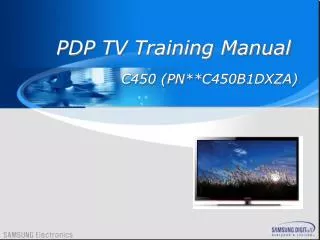
PDP TV Training Manual C450 (PN**C450B1DXZA)
Agenda • Inside of C450 • Specification Comparison to Old Model • Board description • Disassembly • Trouble Shooting
Inside of C450
Control & Connection Panel Viewing the Control Panel
Control & Connection Panel Using an HDMI / DVI Cable : HD connection
Control & Connection Panel Using a Component or Audio/Video Cable
Control & Connection Panel Using an Optical or Audio Cable Connection
Control & Connection Panel Using an Anynet +
Remote control See The Picture on Next page. It is the latest.
SMPS voltage adjust Adjust SMPS Voltage when change SMPS Vs VE Va
Specification Comparison To Old Model
BOARD DESCRIPTION
LVDS 31p FFC HD SATURN4 PDP PCB LAYOUT (192x122, 4L, Normal) 192 LVDS 31P FLASH SMPS SATURN4 SIDE HDMI JACK DDR SPEAKER AUDIO AMP HDMI JACK USB JACK CHANNEL 122 TUNER FUNCTION HDMI JACK PC JACK AV/ COMPONENT JACK
IV. Disassembly DISASSEMBLY
IV. Disassembly ASSY STAND P-BASE & Rear Cover
IV. Disassembly ASSY BRACKET P-SUPPORT STAND
IV. Disassembly SMPS-PDP TV
IV. Disassembly ASSY PDP MODULE P-LOGIC MAIN BOARD
IV. Disassembly ASSY PDP MODULE P-X MAIN BOARD
IV. Disassembly ASSY PDP MODULE P-X MAIN BOARD
IV. Disassembly ASSY PDP MODULE P-Y MAIN BOARD
IV. Disassembly ASSY PDP MODULE P-Y MAIN BOARD
V. Trouble Shooting TROUBLE SHOOTING
V. Trouble Shooting CONTENTS • Power Trouble Shooting • Analog Part • Digital Part • Sound Part • Flow Chart & Waveforms • White Balance • Access Service Mode
Check List for Initial Operation -. Power cord into the set -. Power switches on -. You can hear the SMPS relay * If you can’t hear the relay, check if you have 5V standby -. Logic Board LED is on * If Logic Board LED doesn’t blink -> Check if the Logic Board LED is on, when 24p power cable is not connected. -. Video on * If no video, check the LVDS cable And LVDS clk/data line
Inform to change the Assembly -. Check the side-label version of the set (important) -. Order parts according to the side-label version -. If you change a part check if there are any service-bulletins for potential settings that need to be changed in the factory menu. Inform about error messages -. If the set is connected to the network and the software is old, the below message will pop up. “ version XXXXX is available, upgrade?” -. Select OK, and you can update your PDP TV’s firmware.
V. Trouble Shooting 1. The sets power is composed of a power board and a main board (small power) 2. Check the connectors between power board and main board 3. Check the main boards power outputs 4. When you check main board power(small power IC), There are two types of power IC. One is PWM type, another is regulator type. PWM type should check after inductor. Regulator type should be checked on the output pin. 5. Check each voltage Check After Inductor Check On Pin Regulator Type 2 PWM Type 1 A) Power Trouble Shooting
V. Trouble Shooting A) Power Trouble Shooting
V. Trouble Shooting Gray Level H-sync 16 Gray Wave Form B) Analog Part 1.It is easy to check analog video signal than digital video signal 2.Use reference signal input ( EX. 16 Gray) 3.Check Signal Level and sync 4.Check Signal path until input of Video decoder ( Tuner → Video Decoder, AV Connecter → Video Decoder) 16 Gray Patten
V. Trouble Shooting B) Analog Part
V. Trouble Shooting 1 Period(50Hz) 1 Period(13.5MHz) 1 Period(15.63kHz) V-Sync Clock H-Sync C) Digital Part 1.It is difficult to check digital video signal because of too fast and small signal 2.Check digital video signal, Use H-sync, V-sync and Clock for basic 3.Each digital video ICs connected with data line, H-sync, V-sync and Clock line 4.Check H-sync period, V-sync period, Clock period 5.If period is out of spec, Change the IC This example is Normal PAL TV signal Sync and Clock
V. Trouble Shooting C) Digital Part
V. Trouble Shooting D) Sound Part If there is no audio,trace the sound path ( Input → Sound Processor → AMP → Speaker ) STV Sound Processor SOUND AMP SPEAKER TUNER VIDEO COMPONENT PC HDMI
V. Trouble Shooting D) Sound Part