Download
1 / 26
260 likes | 393 Views
Reconfigurable Communication System Design. Anthony Gaught Advisors: Dr. In Soo Ahn and Dr. Yufeng Lu Department of Electrical and Computer Engineering Bradley University Peoria, Illinois November 13, 2012. Outline. Motivation Brief Theory of QPSK Project Overview Project Description

E N D
Reconfigurable Communication System Design Anthony Gaught Advisors: Dr. In Soo Ahn and Dr. Yufeng Lu Department of Electrical and Computer Engineering Bradley University Peoria, Illinois November 13, 2012
Outline • Motivation • Brief Theory of QPSK • Project Overview • Project Description • Project Milestones • Simulation • Project Status • Conclusions • References
Motivation • Software defined radio (SDR) has advantages over traditional communication systems. • Design a reconfigurable digital communication system using FPGA. • QPSK system is studied for the project.
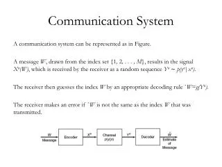
Brief Theory of QPSK • Binary phase shift keying (BPSK) is a modulation scheme which transmits one bit of data per symbol. • Quadrature phase shift keying (QPSK) cuts the bandwidth necessary to transmit data in half when compared to BPSK. • QPSK’s bit error performance is the same as that of BPSK due to orthogonality of the I and Q carriers used in QPSK. • QPSK is used in many applications such as cell phones, satellite communication, cable modems, and others.
Brief Theory of QPSK • s(t) = I(t)*cos(2πfot) – Q(t)*sin(2πfot) • Each symbol represents two bits of data. • I and Q bits are determined based on the phase of the received symbol.
Project Overview • This project implements a QPSK communication system consisting of both a transmitter and a receiver. • The system is designed using VHDL and is implemented on Xilinx Spartan 3E FPGAs. • Allows for flexible transmission data rates.
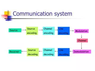
Project Descriptionat the transmitter • Two-bit random data is generated. • The data is split into In-phase (I) and quadrature-phase (Q) components. • The data is shaped using raised cosine filters. • The data is over sampled. • The data is modulated by cosine and sine carriers. • The modulated signals are combined for transmission.
Project Descriptionat the receiver • The received signal is demodulated by local cosine and sine carriers. • The data passes through a matched filter. • The data is down sampled. • The data is fed into a threshold device. • The output is displayed on an oscilloscope.
Milestone One • The receiver and transmitter will be implemented on a single FPGA. • The transmitter is connected directly to the receiver. • A digital to analog converter (DAC) will be used to display data.
Milestone One Block Diagram I = transmitter side in-phase Q = transmitter side quadrature phase I_r = receiver side in-phase Q_r = receiver side quadrature phase S(n) = internal signal from transmitter to receiver
Milestone Two • The receiver and transmitter will be implemented on different FPGA boards. • Data will pass through an (ADC) and a DAC in this milestone. • A carrier recovery circuit and phase locked loop will be implemented in the receiver. • Adverse affects caused by channel imperfections will be explored.
Milestone Two & Three Block Diagram I = transmitter side in-phase Q = transmitter side quadrature phase I_r = receiver side in-phase Q_r = receiver side quadrature phase S(t) = signal from transmitter to receiver
Milestone Three • High speed ADC and DAC modules will be used to connect the transmitter and receiver for assessing overall system operations. • Bit error rate of the system will be used to evaluate the overall system performance.
Simulation Results • I and Q data at the transmitter
Simulation Results • The I and Q data are shaped using a set of raised cosine filters for controlling intersymbol interference. Impulse Response of Raised Cosine Filter
Simulation Results • The recovered I and Q after being filtered are identical to theoretical results from MATLAB simulations.
Simulation Results • The demodulated I and Q data match up with their theoretical results.
Simulation Results • The demodulated I and Q data are then resized to bring the amplitude into a usable range for the Spartan 3E.
Simulation Results • Received I and Q data appear as a constellation of 4 groups of points which matches the theoretical results well.
Simulation Results • Transmitted and received I and Q data.
Simulation Results • The transmitted and received I and Q data after being cleaned up by using a threshold device.
Project Status • Milestone one has been completed. • Preliminary work for Milestone two has begun. • One of the biggest obstacles will be the implementation of the phase locked loop.
Schedule • 1/24 - 2/07 phase locked loop and carrier recovery implementation • 2/14 - 2/21 system optimization and evaluation • 2/28 - 3/07 high speed ADC and DAC implementation • 3/14 - 3/28 system evaluation • 4/04 – 5/02 TBA note: the Bradley expo and project presentation will occur during this period.
Conclusions • FPGA design is flexible to build digital communication systems. The methods used for modulation can be reconfigurable. • The system has a fast design turn-around time compared to conventional design using specialized hardware or DSP processors. • SDR capabilities are to be investigated and demonstrated in the project.
References • Anton Rodriguez, and Michael Mensinger Jr., “Software-defined Radio using Xilinx”, Senior Project Report, Department of Electrical and Computer Engineering, Bradley University, Peoria Illinois, May 2011. • Anthony Gaught, “Software-defined Radio Symbol Generator”, Junior Project Report, Department of Electrical and Computer Engineering, Bradley University, Peoria Illinois, May 2012. • Anthony Gaught, Alexander Norton, and Christopher Brady., “FPGA-based 16 QAM communication system”, EE 568 Report, Department of Electrical and Computer Engineering, Bradley University, Peoria Illinois, April 2012. • Leon Couch, “Digital and analog communication systems”, 8th ed., Boston: Pearson, 2013. • Charles Roth Jr., and Lizy John, “Digital systems design using VHDL”, 2nd ed., United States: Thomson, 2008. • Spartan-3E Data Manual, Xilinx, San Jose, CA,2009.