Download

1 / 21
210 likes | 334 Views
The Post-Moog Digitally Controlled Analog Synthesizer (PM-DCAS) group aims to develop a modular audio synthesis system that bridges classic analog sounds with modern digital control. Key features include MIDI input support, an innovative user interface for easy manipulation of audio parameters, and a reliable system for storing and recalling presets—all while maintaining low material costs. This synthesizer targets hobbyist musicians and synth enthusiasts, providing them with a versatile and user-friendly platform for creative expression.

E N D
The Post-Moog Digitally Controlled Analog Synthesizer Group Members PM-DCAS • Logan Snow • Robert Estelle • Greg Hartl • Toan Ho
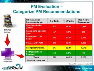
Project Summary • Technical Objectives • Create a modular audio synthesis system • Support MIDI input • Create an innovative user interface • Support storage and recall of presets • Maintain a low material cost • Motivation • Target hobbyist musicians and synth enthusiasts • Recreate classic analog sounds
System Design User Interface Digital Control Board System Interface Board MIDI Keyboard Output Amplifier Analog Synthesis Hardware Debug Monitor
User Interface Attack Decay Sustain Release • Noise Level • Sine • Saw • Tri Duration • Rect Pulse Width Vibrato Center Resonance Volume Options Filter Mode Modulation Variance Filter LPF HPF Fixed Tri BPF Sine P1 P2 P3 P4 Save
RKA – Rotary Knob Assembly • Each digital rotary encoder is read by a dedicated microcontroller (PIC16F87) • LEDs indicate position of knob to user • Display can be reset by master microcontroller to indicate new position PICTURE HERE
DCB - Digital Control Board MIDI Input DACs PICTURE HERE Master Microcontroller (PIC24FJ64GA002) Debug Port SIB Connector Rotary Knob Connectors
Master Microcontroller • Microcontroller reads inputs: • MIDI from external music device • Rotary knob positions through I2C • Debug commands from serial port • Microcontroller sets outputs: • LED positions using I2C LED drivers • Analog control voltages using I2C DACs • All digital control occurs on two I2C busses
Digital Control Scheme … … LED Driver Slave Microcontroller LED Driver … MIDI Keyboard Master Microcontroller I2C DAC I2C DAC … Debug Monitor VCO Control Filter Resonance Other Control Voltages
SIB – System Interface Board I’m a big picture of the SIB + VCO VCA1..4 VCF Noise VCA5 VCA6 • Receives control signals from the DCB • Connects to the power supply • Routes all signals between the analog boards • Mixes the intermediate signals Output
Analog Signal Flow + VCO VCA1..4 VCF Noise VCA5 VCA6 Output
VCO – Voltage Controlled Oscillator I’m a big picture of the VCO + VCO VCO VCA1..4 VCF Noise VCA5 • 1V/Octave control input • At least 3 Octave range • Several Outputs: • Sine wave • Sawtooth wave • Rectangular wave with PWM • Triangular wave • Each output has corresponding VCA VCA6 Output
Noise Source + I’m a big picture of the noise source VCO VCA1..4 VCF Noise Noise VCA5 VCA6 • White noise • Adjusted through a VCA before mixing with other signals Output
VCA – Voltage Controlled Amplifier I’m a big picture of the VCA + VCO VCA1..4 VCF Noise VCA5 VCA6 • Logarithmic amplitude control voltage • Three boards with two amplifiers each • VCA1..4 modulate VCO outputs • VCA5 is dedicated to the noise source • VCA6 output connects to final synthesizer output Output
VCF – Voltage Controlled Filter + VCO VCA1..4 I’m a big picture of the VCF VCF VCF Noise VCA5 • Voltage-controlled resonance and center frequency • Multiple Filter Outputs • High Pass • Low Pass • Band Pass VCA6 Output
Analog Signal Flow + VCO VCA1..4 VCF Noise VCA5 VCA6 Output
Issues Encountered • Shipping problems • Solder flux disaster • Old SIB revision sent for fabrication • Post-fabrication board modifications • Pin size mismatches on DCB
Planned Demonstration • MIDI input from a music keyboard • Auditory verification of audio parameter manipulation • Visual verification of user interface correlation with audio parameter adjustment • Saving and loading of presets