Download
1 / 51
830 likes | 1.54k Views
Microphones and Loudspeakers. Architectural Acoustics II April 3, 2008. Final Exam Reminder. Wednesday December 10 3:00 – 6:00 Greene 120 (this building, first floor) Handwritten notes on 2 sides of 8.5” x 11” paper are allowed, along with a calculator No laptops. Transduction.

E N D
Microphones and Loudspeakers Architectural Acoustics II April 3, 2008
Final Exam Reminder • Wednesday December 10 • 3:00 – 6:00 • Greene 120 (this building, first floor) • Handwritten notes on 2 sides of 8.5” x 11” paper are allowed, along with a calculator • No laptops
Transduction • Conversion of one form of energy into another • For microphones: acoustical → electrical • For loudspeakers: electrical→ acoustical • Two basic categories of transducers • Sensors • Small • Low power • Don’t affect the environment they are sensing • Actuators • Large • High power • Meant to change the environment they are in
Simple EE Review • V = I·R (Ohm’s Law) • V = voltage (volts) • I = current (amperes) • R = resistance (ohms) • V = B·l·u (Electromagnetic induction) • V = voltage • B = magnetic field (Teslas) • l = length of wire (m) • u = wire or magnet Velocity (m/s) Rossing, The Science of Sound, Figure 18.2, p. 370 http://www.tiscali.co.uk/reference/encyclopaedia/hutchinson/images/c01347.jpg
Simple EE Review • Capacitors (formerly known as condensers) • Q = C·V • Q = charge (coulombs) • C = capacitance (farads) • V = voltage (volts) • C A/d • A = area of the capacitor plate (m2) • d = plate separation distance (m) Image from http://upload.wikimedia.org/wikipedia/en/b/b5/Capacitor.png
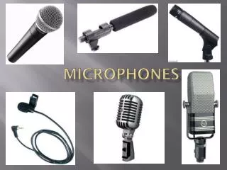
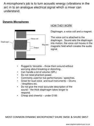
Basic Microphone Types • Dynamic (moving coil) • Condenser (capacitor) • Electret • Ribbon • Piezo-electric (crystal or ceramic)
Dynamic Microphone • Sound pressure on the diaphragm causes the voice coil to move in a magnetic field • The induced voltage mimics the sound pressure • Comments • Diaphragm and coil must be light • Low output impedance – good with long cables • Rugged V = B·l·u Long, Fig. 4.1, p. 116, 2nd image courtesy of Linda Gedemer
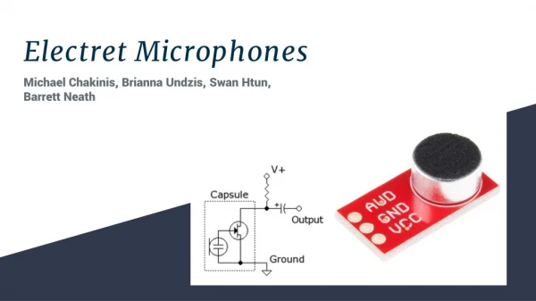
C A/d Condenser Microphone • Diaphragm and back plate form a capacitor • Incident sound waves move the diaphragm, change the separation distance, change the capacitance, create current • Comments • Requires a DC polarizing voltage • High sensitivity • Flat frequency response • Fragile • High output impedance, nearby pre-amp is necessary Q = C·V
C A/d Electret Microphone • Same basic operation principle as the condenser mic • Polarizing voltage is built into the diaphragm • Comments • High sensitivity • Flat frequency response • Fragile • High output impedance, nearby pre-amp is necessary Q = C·V Long, Fig. 4.1, p. 116
Ribbon Microphone • Conductive ribbon diaphragm moving in a magnetic field generates an electric signal • Comments • Lightweight ribbon responds to particle velocity rather than pressure • Both sides are exposed resulting in a bidirectional response • Sensitive to moving air • Easily damaged by high sound-pressure levels Long, Fig. 4.1, p. 116, 2nd image courtesy of Linda Gedemer
Piezo-Electric Microphone (a.k.a. Crystal or Ceramic Microphone) • Diaphragm mechanically coupled to a piezoelectric material • Piezo (lead zirconate titanate (PZT), barium titanate, rochelle salt) generates electricity when strained • Comments • No polarization voltage • Generally rugged • See Finch, Introduction to Acoustics, Chapter 7, “Piezoelectric Transducers” for details Long, Fig. 4.1, p. 116
Microphone Parameters 1/2-inch diameter B&K measurement microphone
Microphone Parameters Neumann U87 Ai Large Dual – diaphragm Microphone Slide courtesy of Linda Gedemer
Frequency Response and Incidence Angle Long, Fig. 4.8, p. 121
Frequency Response and Incidence Angle Off-axis coloration Slide courtesy of Linda Gedemer
Transient Response Slide courtesy of Linda Gedemer
Other Microphone Types Shotgun Microphone Rossing, The Science of Sound, Figure 20.10, p. 398 http://aes.harmony-central.com/115AES/Content/Audio-Technica/PR/AT897.jpg
Other Microphone Types Parabolic Microphone http://homepage.ntlworld.com/christopher.owens2/Images/TelingaMount.jpg http://hyperphysics.phy-astr.gsu.edu/hbase/audio/mic3.html
Other Microphone Types Contact Microphones www.BarcusBerry.com
Other Microphone Types Pressure Zone Microphone (PZM) www.crownaudio.com www.shure.com Slide courtesy of Linda Gedemer
Use of Boundary Mics Slide courtesy of Linda Gedemer
Effects of Floor Reflections Slide courtesy of Linda Gedemer
Soundfield Microphone • 4 diaphragms in a tetrahedral pattern • Essentially measures omni pressure (W) and X,Y, and Z-dimension pressure • Used for 1st-order spherical harmonic encoding of a sound field (1st-order Ambisonics) http://www.soundfield.com/soundfield/soundfield.php
9.9 cm 0.2 cm Microphones and Diffraction Blackstock, Fundamentals of Physical Acoustics, Figure 14.12, p. 487
Directivity Patterns • Single-diaphragm microphones are typically constructed to have one of a variety of directivity patterns • Omni directional • Bidirectional • Cardioid • Hypercardioid • Supercardioid • General mathematical form A + B·cos(θ)
Directivity and Ports • In a directional (ported) microphone, sound reflected from surfaces behind the diaphragm is permitted to be incident on the rear side of the diaphragm. • Sound reaching the rear of the diaphragm travels slightly farther than the sound at the front, and it is slightly out of phase. The greater this phase difference, the greater the pressure difference and the greater the diaphragm movement. As the sound source moves off of the diaphragm axis, this phase difference decreases due to decreasing path length difference. This is what gives a directional microphone its directivity. Shure Pro Audio Technical Library
Directivity Patterns Omnidirectional Bidirectional Cardioid
Omni Bidirectional Cardioid Hypercardioid Supercardioid Directivity Patterns Hypercardioid Supercardioid All Five
Directivity in 3D Omnidirectional Bidirectional Cardioid Slide courtesy of Linda Gedemer
Directivity in 3D Supercardioid Hypercardioid Slide courtesy of Linda Gedemer
Combining Patterns: Dual Capsules Neumann U87Ai Georg Neumann GmbH Slide courtesy of Linda Gedemer
Basic Cone Loudspeaker Principles • Paper (or other light-weight material) cone attached to a coil suspended in a magnetic field • Audio signal (voltage) is applied to the wire, causing it to move • Mechanism is enclosed to prevent dipole radiation • Typical characteristics • Sensitivity • Impedance • Frequency response • Directivity Rossing, The Science of Sound, Figure 20.13, p. 402
Average intensity (I) if total power (W) is radiated uniformly over a spherical surface. Speaker Directivity • Directivity Factor • I usually measured on axis • Directivity Index
Speaker Directivity Slide courtesy of Linda Gedemer
Speaker Parameters JBL Control 29 AV-1 Slide courtesy of Linda Gedemer
Speaker Parameters JBL Control 29 AV-1 Slide courtesy of Linda Gedemer
Enclosures Direct radiator or Acoustic suspension Bass reflex Bass reflex with passive radiator Bass reflex with acoustic labyrinth Slide courtesy of Linda Gedemer
Cabinets and Diffraction Svensson and Wendlandt, “The influence of a loudspeaker cabinet’s shape on the radiated power”, Baltic Acoustic 2000.
Cabinets and Diffraction Svensson and Wendlandt, “The influence of a loudspeaker cabinet’s shape on the radiated power”, Baltic Acoustic 2000.
Cabinets and Diffraction Svensson and Wendlandt, “The influence of a loudspeaker cabinet’s shape on the radiated power”, Baltic Acoustic 2000.
Cabinets and Diffraction Svensson and Wendlandt, “The influence of a loudspeaker cabinet’s shape on the radiated power”, Baltic Acoustic 2000.
Array Behavior • Proper calculations • Far-field approximations • Change in behavior with number of elements • Change in behavior with phasing • Change in behavior with spacing • Change in behavior with frequency
R r1 r2 r3 r4 rn … 1 2 3 4 n Array of n elements (loudspeakers or microphones) Array Calculations • p(R) = pressure at position R • A = agglomeration of various constants • ri = distance from element i to position R • e-jkr - δ=Green’s function for a point element • k = wavenumber • δ = phase • Sweep R in an arc centered at the center of the array to create a polar directivity plot. • This expression does not account for the directivity of individual elements in the array! All are assumed to be point sources or omnidirectional microphones.
Far-Field Approximation • I = intensity of the array • n = number of array elements • β = kd·cos(θ) – δ • k = wave number • d = distance between array elements • θ = angular position relative to the center of the array • δ = constant phase difference between elements
Intensity vs. Log Magnitude Intensity Log Magnitude 8 elements at 10 cm spacing, 1 kHz, R at 10 m
2 4 8 16 Number of Elements
Phase (between elements) 0º 60º 110º 140º
Frequency 1 kHz 500 Hz 4 kHz 2 kHz
Spacing 10 cm 5 cm 40 cm 20 cm