Download
1 / 10
100 likes | 263 Views
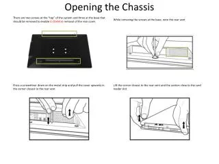
Opening the Chassis. There are two screws at the “top” of the system and three at the base that should be removed to enable to (Delete) removal of the rear cover. . While removing the screws at the base, note the rear vent.

E N D
Opening the Chassis There are two screws at the “top” of the system and three at the base that should be removed to enable to (Delete)removal of the rear cover. While removing the screws at the base, note the rear vent Press a screwdriver down on the metal strip and pull the cover upwards in the corner closest to the rear vent Lift the corner closest to the rear vent and the section close to the card reader slot
Installing the Desktop Board If the system has been configured previously, ensure that the system fan is disconnected before complete removal of the rear cover. When inserting the IO shield, ensure that it is orientated correctly When using the Intel® Thermal Solution and the Intel® DH61AG Desktop board in this system, ensure that the thermal retention mechanism is in place before installing the desktop board “Unscrew” the internal speaker closest to the LVDS connection to create more space when installing the desktop board and the LVDS connector (How do they know what an LVDS connector is?)
General Installation Notes When installing the desktop board, it may help to locate the power connection on the desktop board with the IO shield first and then “swivel” the board in. This is useful when ensuring that the connection with the IO shields make the correct contact with specific ports (Don’t understand this at all) Don’t lose the small bracket and screws that are used to attach the ODD drive. The power cable for the ODD drive is spliced rom (?)the HDD SATA connector Please note the orientation of the Card Reader Cable (8), the power cable should be connected to the pin “furthest” from the “missing pin” used to key a double USB connection.
General Installation Notes When inserting the LVDS Connector, ensure correct alignment. In (Delete), Never remove the cable by “pulling on the wires” as this could permanently damage the cable. Where a “single” USD connection is connected to a “double” USD header, ensure that the “red” cable is aligned to the pins closest to PIN 1 (white marking at the base). It is possible to connect two singe USB connections to a double USB header this way. When installing the Intel® Thermal Solution, align the screws correctly and make sure that the fan and heat sink are properly aligned. Make sure that you connect the stand correctly to the compute (Change to computer)unit. If the retention screw is not in place, the stand may accidentally (Add) be disconnected when the unit is moved.
System Overview All cables are labeled to support quick configuration
Connecting Cables to the Intel® DH61AG Board Connect the cables as they are labeled with the matching connector on the Intel® DH61AG Desktop board. Please note the orientation of the Card Reader cable (8)
Display Panel Jumpers Before plugging in any cables, confirm the voltage selection jumpers for the Backlight Inverter and LCD Panel are set correctly for the AIO system being integrated. The default settings for the board are: FPD Voltage Selection: 5V & Backlight Inverter Voltage Selection: 19V These settings apply to the Loop LP2150 AIO Unit.
LVDS (Low Voltage Display Connector) Insert the flat silver ribbon cable with a 40-pin LVDS connector into the LVDS port on the top surface of the motherboard. (Note: there is another similar looking port on the bottom side which is eDP – embedded display port) To ensure the connector is all the way in, use a screwdriver head to push in both ends of the connector. C:LDVS D:eDP
Installing the 2.5” Hard Drive or SSD Installing the 2.5 Drive is a 3 step process: Remove the HDD Cage from the chassis pan, slide the drive into the cage and secure it with the 4 screws provided with the chassis, then install the cage back in the chassis pan with the 3 screws.
Using Intel® Integrator Toolkit to Enable Flat Panel Display • Ensure Latest BIOS is installed • Create a file with a .INI extension and include the following text: [System] INIversion=2.9 [SETTING_0772] Value=1 [SETTING_05FF] Value=3 • Connect a secondary monitor to the DVI or HDMI port on the desktop board • Boot the system to DOS using DOS bootable Media (typically USB Flash Drive) • Ensure that ITOOLKIT.EXE and the INI file are available on the bootable media • Run the command itoolkit install –tokens –ini=YourFileName.ini • Restart the system press F2 to enter BIOS Setup (The Flat Panel Display should display the BIOS Splash Screen) • Navigate to Configuration | Video | Advanced Flat Panel Display Settings • For EDID Data Source select Type 08: 1366x768 (for the Gigabyte GB-EABN with 18.5 Inch Panel) • For LVDS interface type select Single Channel • For Color Depth select 24-bpp (default) • Press F10 to save settings and exit BIOS configuration • Once the panel settings are confirmed to work correctly, if you wish to lock the Flat Panel Display Settings, reboot to the BIOS, navigate to Configuration | Video | Advanced Flat Panel Display Settings and select the Lock option for Flat Panel Configuration Changes. Please Note: Once flat panel configuration changes are locked, they can only be unlocked using Intel® Integrator Toolkit – this step is not mandatory, it merely prevents potential user error in changing panel settings that could require the completion of the above steps. If you are using an HDMI port, this value should be set to 5 • Please Note: For more information on using Intel® Integrator Toolkit and downloading the latest BIOS versions , please go to: http://www.intel.com/Products/Desktop/Motherboards/db-dh61ag/DH61AG-tools.htm