Download

1 / 23
240 likes | 485 Views
NCore Calibration Issues Meeting the new QC Requirements. Lewis Weinstock and Dennis Mikel EPA Office of Air Quality, Planning and Standards. Key Topics. Overview of NCore technical requirements Mass Flow Controllers (MFC) Calibrators Compressed Gas Cylinders Zero Air Generators

E N D
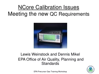
NCore Calibration IssuesMeeting the new QC Requirements Lewis Weinstock and Dennis Mikel EPA Office of Air Quality, Planning and Standards
Key Topics • Overview of NCore technical requirements • Mass Flow Controllers (MFC) Calibrators • Compressed Gas Cylinders • Zero Air Generators • Summary
NCore Calibration Challenges • Operating analyzers on lower ranges where ambient data are more affected by instrument drift and interferences • Old CO range 0 – 50 ppm for NAAQS compliance • Typical NCore CO range 0 – 5 ppm or even lower • More frequent QC checks advised so calibration automation is important • Integration of data systems and calibrators important for QC validation and timely reporting of problems • Calibration standard certification periods are shorter for lower concentration standards • Zero air purity is more critical than ever • Reviewing your calibrator capabilities and potentially upgrading hardware may be the most important part of designing and implementing a successful NCore gas monitoring system
NCore Calibration and QC Check Requirements • QC Checks (Precision): • Required (40 CFR 58 Appendix A) • Minimum: Once every two weeks – daily is recommended • Daily Level 1 Zero and Spans recommended • Multi-point calibrations: • Quarterly (according to TAD) or if drift is an ongoing issue • Draft MQO Table - 1 in 6 months, upon instrument startup, repair, or exceeded drift tolerance • MDL Tests (New requirement): • Annually or after major analyzer repair • Consider entire system when troubleshooting QC problems – zero air or calibrator issues may be the cause • Don’t just recalibrate repeatedly when analyzer drift and/or linearity problems are indicated
Calibration and QC Check Concentrations* * For a typical urban NCore station
Method Detection Limit Test(How do you run it?) • Use a concentration of 2.5 to 5 times the instrument signal/noise • Run zero gas through analyzer • Dilute the calibration gas to estimated concentration level and collect readings for a predetermined length of time: • Suggested: 20-25 1 minute observations, repeated 7 times over the course of 5 -14 days. Average the concentration from these readings. • Calculate the MDL as: Where represents the 99th quantile of a Student’s t distribution with (n-1) degrees of freedom and n represents the number of replicate measurements and s is the standard deviation.
Method Detection Limit Test • Confirms that a trace-level analyzer is really performing as a trace level • Perform as part of acceptance testing • Annually as part of regular QA program • After a major repair such as detector replacement • Operational challenges • Need to accurately and repeatedly generate a very small concentration • Will need dedicated low-level gas cylinder standards in the 1 ppm range for NO and SO2, and 10 ppm range for CO • Agencies can share cylinders • Possible development of cylinder “bank” • Dilution challenges capacity of zero air scrubbing system at high flows (~ 20 LPM)
Example Method Detection Limit Test Student's t-distribution From Wikipedia, the free encyclopedia MDL = (2.764) * 5.26 = 14.54 ppb
Typical Mass Flow Controller (MFC) TheoryCalibrator Diagram Zero Air MFC
Calibrator Critical Specifications • Gas Flow – 0 to 100 cc/min • Air Flow – 0 – 20 L/min • Multiple Gas ports - optional • Built in traceable ozone generator • Accuracy +/- 1% Full Scale • Precision +/- 1% Full Scale • Linearity +/- 1% Full Scale Environics 9100
Calibrator Specification Matrix (EPA Research 2006) * Highest optional ranges. ** Tanabyte offers a 0 – 20 lpm option
Calibrator Critical Features • Option for multiple gas flow controllers to expand dynamic dilution range • Want to stay away from flows less than 10% or greater than 90% of MFC full scale • Internal calculation of MFC flow response • Programmable scheduled tasks • Remote access and control ready (accept direct digital commands) • Digital Inputs – controlled by remote access • Digital Outputs – signals to remote device • Capability to directly control solenoids without external power supplies
Certifying your Calibrator Flows • Initial calibration should be provided with purchase – always recheck after delivery • Certify flow controllers against a NIST traceable flow device (such as a Bios DryCal, Gilibrator or Hastings Bubble Kit or other flow device) • NIST Traceable flow device should be certified annually (or if you suspect a problem) • Perform quarterly or semi-annual checks of your MFCs (or until establish trend) • Calculate observed flow vs set points at STP (25 degrees Celsius and 760 mm Hg)
MFC Calibration - Burdens Creek (1-23-2007)Environics 9100 #A50930
MFC Calibration - Burdens Creek (1-23-2007)Environics 9100 #A50930
Compressed Gas Cylinders - Features • Come in variety of sizes (size 50 or 150) • Recommend using Aluminum cylinders • Get EPA Protocol certification from experienced vendors • http://www.epa.gov/appcdwww/pubs/600r97121/600r97121.htm • Note: certification periods can be shorter than expected for low concentration cylinders (next slide) • Use Stainless Steel regulators and cylinder valves • Use Stainless steel or Teflon lines from Regulator to MFC (Teflon recommended) • Recommended Cylinder Concentrations for the NCore Sites: • SO2: 10 – 15 ppm • NO: 10 – 30 ppm • CO: 200 – 300 ppm • Oxygen free - Balance Nitrogen
Zero Air Source - Issues • The air system should be able to provide clean air below the stated Lower Detection Limits (LDL) of the instruments you are operating at maximum required flow rates (up to 20 l/min) • NO: 50 ppt • SO2: 100 ppt • CO: 40 ppb • Check the specifications before you purchase • Regularly maintain/replace scrubbing materials T_API Model 701 TEI Model 111
Zero Air Generation - Issues Ultra Pure Cylinder Air vs. Zero Air Generators Trade off: Quantity Used vs. Costs for cylinders • High flow rates • Humidity issues • Purity of air generated • Use Ultra Pure Cylinder air to verify Generator purity (recommended)
Summary • QC Checks and calibrations are required for NCore Monitoring Stations • The MFC systems available today are compatible with the PG instruments and support a high degree of automation • Calibration systems should be regularly flow certified with NIST-traceable devices • Lower concentrations cylinders are required since PG instruments have lower ranges and levels of detection • Gas cylinders should be certified – EPA Protocol • Zero air generators should be able to “scrub” below the LDLs of the PG instruments