Download
1 / 60
640 likes | 944 Views
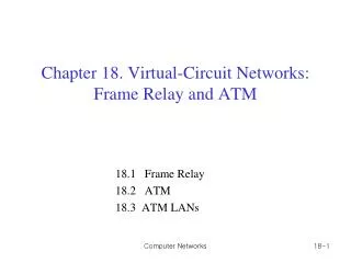
Virtual Circuit Networks. Frame Relays. Background. Frame Relay is a Virtual Circuit WAN that was designed in late 80s and early 90s. Prior to Frame Relays organizations were using Virtual Circuit Switching Networks called X.25. Background. Drawbacks of X.25: 1. Low data rate – 64 kbps

E N D
Virtual Circuit Networks Frame Relays
Background • Frame Relay is a Virtual Circuit WAN that was designed in late 80s and early 90s. • Prior to Frame Relays organizations were using Virtual Circuit Switching Networks called X.25
Background • Drawbacks of X.25: 1. Low data rate – 64 kbps 2. Extensive flow and error control at both data link layer and network layer. 3. Originally designed for private use – has its own network layer. Doubles the overhead.
Background • As a result some organizations start private WANs leasing T-1 and T-3 lines from public service providers. • Here if n branches are there then n(n-1)/2 lines are required – very costly. • Assume fixed rate data and not allowbursty data. • Bandwidth on Demand not available. • In Response to this Frame Relay was designed.
Features • Operates at a higher speed – (1.544Mbps and recently 44.376 Mbps) • Operates on just physical and data link layers – used as a backbone network. • Allows bursty data. • Allows a frame size of 9000 bytes. • Less expensive than other WANs. • Has error detection at Data link layer only. No flow control or error control.
Architecture • Frame Relay provides Permanent Virtual Circuits and Switched Virtual Circuits. • Frame Relay is identified by DLCI (Data Link Connection Identifier ). • DLCI is similar to VCI in Virtual Circuits.
Architecture • PVC versus SVC PVC: Table entries done by administrator. Drawbacks: Costly – both parties should pay for connection Connection is created from one source to one destination only.
Architecture • SVC : It creates a temporary short connection that exist only when transferring the data. Drawbacks : It requires establishing and terminating phases. Switches: Each switch has a table to route Frames having incoming port, DLCI and outgoing Port, DLCI combinations.
Frame Relay Layers • Has only two layers. • Physical layer supports any of the protocols supported by ANSI. • Data link layer does not support error or flow control but has only error detection. • error or flow control must be provided by the higher layers.
Extended Address • To increase the range of DLCIs The Frame Relay address can be extended from 2 bytes to 3 or 4 bytes. • EA = 1 means Final byte otherwise some byte to follow. • In 3 and 4 byte formats the bit before the last bit is 0.
Other Features • FRAD : To handle frames arriving from other protocols it uses a device called Frame Relay Assembler / Disassembler. It can be implemented as a separate device or as a part of a switch.
Other Features • VOFR : Frame Relay Networks offer an option called Voice Over Frame Relay to send voice through the network. Voice quality is not that good as Circuit switched networks.
Other Features • LMI: To provide more management features a protocol called Local Management Information Protocol is added recently. It is used for controlling and managing Interfaces. Congestion control and Quality of Service: Other nice feature added
ATM • Asynchronous Transfer Mode is the Cell Relay Proticol designed by ATM Forum and adopted by ITU-T. • Combination of ATM and SONET gives you the information Superhighway. • ATM was introduced at the right time.
Design Goals • Need for a transmission system to optimize the use of a high data rate transmission media. • The system must interface with existing systems (networks) and existing telecommunication hierarchies. (local loops, local providers etc.) • The design must be cost effective so it can reach every user. • The new system must be connection oriented to ensure accurate and predictable delivery. • Move the functionalities to hardware as for as posible.
Background • PROBLEMS WITH EXISTING SYSTEMS: In Frame Networks, different protocols use frames of varying size and complexity. So larger and larger headers are needed compared to data. As a result some protocols enlarged the size of data which may lead to wastage.
Background Handling variable frame size is very difficult. Difficult to provide consistent data rates. Audio and Video frames are normally small in size, mixing them with conventional data may lead to unacceptable delays.
Cell Networks • In Cell Networks a Cell is the basic unit of Data exchange. • A Cell is a small data unit of fixed size which can be transmitted with complete predictability and uniformity. • Cells can be multiplexed with other cells. • Cells from different sources are interleaved to avoid long delays. • The cells reach their destinations as approximation of a continuous stream. So can be used for real time transmission.
Asynchronous TDM • ATM uses Asynchronous TDM to multiplex cells from different channels. • ATM Multiplexers fill the slot with a cell from any input channel that has a cell.
Why fixed cell size? • It is easier to build the hardware switches to do simple jobs. • We can embed parallelism which greatly improves the scalability of switch design. • Cells create shorter queues. So we can have finer control over the behavior of the queues. (less delay for all packets) • A cell in ATM is 53 bytes long with 5 bytes header and 48 byte payload.
Architecture • ATM is a cell switched network. • Endpoints are connected to the switches through UNIs (user to network interface) and switches are connected through NNis (network to network interfaces).
Virtual Connections • Connection between endpoints is through TPs , VPs and VCs. • A Transmission path is the physical connection between an endpoint and a switch or between two switches. • TP is divided into several Virtual Paths.
Virtual Connections • A Virtual Path provides a connection or a set of connections between two switches. • A Virtual Circuit is the one which logically connect two points • Cell Networks are based on VCs. • All Cells belonging to a single message follow the same VC and remain ih their original order till they reach their destination.
Identifiers • A Virtual connection is identified by a pair of numbers (Identifiers) VPIs and VCIs. • All Virtual connections that are bundled into one VP have same VPI. • The lengths of VPIs are different for UNIs and NNIs UNI – 8 bits VPI and 16 bits VCI (24 bits) NNI – 12 bits VPI and 16 bits VCI (28 bits) With VPIs and VCIs we can achieve Heirarchical routing.
Connections • ATM uses two types of connections – PVC or SVC. • In PVC the network provider will fill the entries of the table. • In SVC to create the connection between endpoints it need network layer addresses so it depends on network layer protocol (IP). • ATM uses switches to route the cell from a source endpoint to the destination endpoint.
ATM layers • ATM standard defines three laters. - Application Adaptation Layer - ATM layer - Physical layer * End points use three layers while switches uses only bottom two layers.
Physical Layer Original design of ATM is based on SONET – Because of two reasons. - High data rate - Boundaries of cells can be clearly defined. Other physical layer technologies can also be used.
ATM Layer: provides Routing, Traffic Management, Switching and Multiplexing services. It takes 48 byte segments from AAL and transform into 53 byte Cells.
It has two header formats – UNI and NNI. GFC – Flow control VPI and VCI – Identification 3 bit Payload Type – 1st Bit – Managerial information 2nd Bit(if 1st is set) – EFCI (explicit forward Congestion Indication) 3rd Bit – User Signaling bit used in AAL5 CLP – congestion control. HEC – Header Error Correction using CRC-8 for first 4 bytes of header.