Download
1 / 35
380 likes | 703 Views
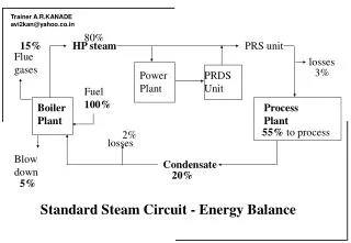
80%. 15%. HP steam. PRS unit. Flue gases. losses. 3%. Power PRDS Plant Unit. Fuel 100%. Boiler Process Plant Plant. 55% to process. 2%. losses. Blow down. Condensate. 20%. 5%. Standard Steam Circuit - Energy Balance. Selection of Working Pressure.

E N D
80% 15% HP steam PRS unit Flue gases losses 3% Power PRDS Plant Unit Fuel 100% Boiler Process Plant Plant 55% to process 2% losses Blow down Condensate 20% 5% Standard Steam Circuit - Energy Balance
Selection of Working Pressure • What is the right pressure for given process • Objective should be process temp. • Heating water to 850C can be achieved using • steam at any pressure above atmospheric. • Would you use steam at - • (a) 2 barg.sat. • Or (b) at 7 barg.sat. • Or (c) superheated at 2barg.2000C? • For indirect heating, latent heat released will be - • (a) 517.6 Kcal/Kg. • (b) 489.9 Kcal/Kg. 5.3% more consumption • (c) 517.6 Kcal/Kg. At a very slow rate
Selection of Working Pressure - contd. For indirect heat transfer process - The right choice is ‘the lowest possible’. Rule of thumb - Pressure giving T(steam) + 350C For Direct heat transfer process - It does not matter so long as you ensure thorough mixing of steam with the product.
Distribute at High Pressure • This will have the following advantages: • Smaller bore steam mains needed and therefore less heat (energy) loss due to the smaller surface area. • Lower capital cost of steam mains, both materials such as pipes, flanges and support work and labour. Lower capital cost of insulation (lagging). • Dryer steam at the point of usage because of the drying effect of pressure reduction taking place near the equipment. • The boiler can be operated at the higher pressure corresponding to its optimum operating condition, thereby operating more efficiently. • The thermal storage capacity of the boiler is increased, helping it to cope more efficiently with fluctuating loads, and a reduced risk of priming and carryover How much reduction in thermal storage capacity of a 10.5 barg rated boiler operated at 7 barg.?
How Do We Pipe Size? Spirax Customer • On the basis of: • Fluid Velocity • Pressure Drop
Pipe Sizing • Greater Cost • Greater Heat Loss • Greater Volume of Condensate Formed • Lower Pressure to Steam Users, or • Not Enough Volume of Steam • Water Hammer and Erosion
Methodsof Steam-pipe Sizing • Velocity Method • For saturated steam system • Ideally suited for Process use • Pressure Drop Method • For superheated steam • Ideally suited for Power Plants & Co-gen units
Methodsof Steam-pipe Sizing - contd. Factors governing the method to be used - Steam Pressure and Temperature Size of distribution network Longer lengths Larger pipe sizes Criticality of pressure drop & th.stresses Mostly for Power plants and HP cogen
Methods of Steam-pipe Sizing • Rules of thumb to be followed - • Maximum velocity 15 m/s for LP wet steam(flash steam) • 25 m/s for sat.steam long lengths • 30 m/s for sat.steam short tappings • 40 m/s for superheated steam • Normal Pressure Drop Less than 10% inlet pressure • Less than 1 Kg/cm2 for given length of piping. • Equivalent length of piping - Add 10% for fittings in the line.
Pipeline Capacities at Specific Velocities Pressure Velocity kg/h bar m/s 15mm 20mm 25mm 40mm 50mm 80mm 100mm 150mm 1.0 15 8 17 29 65 112 260 470 1020 25 12 26 48 100 193 445 730 1660 40 19 39 71 172 311 640 1150 2500 4.0 15 19 42 70 156 281 635 1166 2460 25 30 63 115 270 450 1080 1980 4225 40 49 116 197 456 796 1825 3120 7050 10.0 15 41 95 155 372 626 1485 2495 5860 25 66 145 257 562 990 2205 3825 8995 40 104 216 408 910 1635 3800 6230 14390
Steam-pipe Sizing Examples Size the line to carry - (a) 300 kgs/hr.steam at 1 barg to FWT 150 m.away (b) 1100 kgs/hr.steam at 10 barg to a drier 300m.away (c) Superheated steam 2TPH at 15 barg.300C to turbine at a distance of 50 m.
Waterhammer - a phenomenon Steam has low density but high velocity WP 10 barg Density 5.5 Kg/m3 Velocity 25m/s Condensate has high density but low velocity WP 10 barg Density 909 Kg/m3 Velocity 3m/s Impact or Momentum = Mass X Velocity Condensate having 160 times mass density travelling at 10 times it’s normal velocity will exert 1600 times greater impact.
Waterhammer SAGGING MAIN Condensate Vibration and noise caused by waterhammer Slug of water from condensate
What is water-hammer? Water-hammer is the hammer like impact due to fluid flow in a pipeline. This can happen in any line carrying two-phase flow Steam lines with lot of condensed steam not properly drained Condensate lines with flashing of condensate in the line. The effect would be - Severe mechanical vibrations Heavy leakages from joints Ruptured pipelines
Cross-Section Steam Correct Condensate Steam trap Pocket 25/30mm Cross-Section Steam Incorrect Ineffective, and Proper Drain Points
Steam Line Reducers Correct Steam Condensate Incorrect Steam
Steam Steam Correct Incorrect Branch Connections Condensate
Drop Leg Main Shut off Valve Trap Set
MAINS SIZE-mm Warm Up Loads/Running Loads(kg)per 50m of Steam Main Figures in italics represent running loads Ambient temperature 200C, insulation efficiency 80%
Nom. Pipe Interval of Horizontal run Interval of Vertical run Size mm. metres metres Steel/Copper Bore O/D Mild Steel Copper Mild Steel Copper 12 15 -- 1.0 -- 1.2 15 18 2.0 1.2 2.4 1.4 20 22 2.4 1.4 3.0 1.7 25 28 2.7 1.7 3.0 2.0 32 35 2.7 1.7 3.0 2.0 40 42 3.0 2.0 3.6 2.4 50 54 3.4 2.0 4.1 2.4 65 67 3.7 2.0 4.4 2.4 80 76 3.7 2.4 4.4 2.9 100 108 4.1 2.7 4.9 3.2 125 133 4.4 3.0 5.3 3.6 150 159 4.8 3.4 5.7 4.1 200 194 5.1 -- 6.0 -- 250 267 5.8 -- 5.9 -- Recommended Support Spacing for Steel Pipes
Rollers for Steel Pipework Twin Pipe Support Bracket Chair & Roller Chair Roller & Saddle
Air Venting • Balanced Pressure • Air Vent Steam Main Thermodynamic Steam Trap with optional Blowdown and for ease of maintenance a universal coupling Air
Temp. diff. Steam to Air Pipe Size 15mm 20mm 25m 32mm 40mm 50mm 65mm 80mm 100mm 150mm o C W/m 54 65 79 103 108 132 155 188 233 324 56 68 82 100 122 136 168 198 236 296 410 67 83 100 122 149 166 203 241 298 360 500 78 99 120 146 179 205 246 289 346 434 601 89 116 140 169 208 234 285 337 400 501 696 100 134 164 198 241 271 334 392 469 598 816 111 159 191 233 285 321 394 464 555 698 969 125 184 224 272 333 373 458 540 622 815 1133 139 210 255 312 382 429 528 623 747 939 1305 153 241 292 357 437 489 602 713 838 1093 1492 167 274 329 408 494 556 676 808 959 1190 1660 180 309 372 461 566 634 758 909 1080 1303 1852 194 Heat Emission from Bare Pipes
Calculation of Heat Transfer Where Q =heat transfer rate (W) U =overall heat transfer coefficient (W/m2K) A =mean surface area (m2) t =temperature difference (K)
THERMAL INSULATION TO REDUCE HEAT LOSS TO PROTECT FROM DAMAGE/BURNS TO PROVIDE WEATHER PROOFING
DESIRED PROPERTIES • THERMAL • TEMP.RESISTANCE • LOW CONDUCTIVITY • MECHANICAL • SHOCK RESISTANCE • POROSITY FOR AIR BINDING • CHEMICAL • INERT ACTIVITY
INSULATION MATERIALS • MINERAL WOOL (IS-3677) • - Most commonly used • GLASS WOOL • - Specified as alternative • CALCIUM SILICATE OR MAGNESIA • - Use as Refractory • ASBESTOS • - Used for small lines
INSULATION MATERIALS WIRENETTING - TO KEEP INSULATION IN PLACE SURFACE COVERING - TO PROTECT INSUL. FROM DAMAGE - GI/AL SHEET OF 22/24g THK. - CEMENT PLASTER - THERMOSETTING COMPOUND
INSULATION APPLICATION METHODS • WIREBRUSHING HOT SURFACES • PREPARATION OF INSULATION MATTRESSES OF CORRECT DENSITY • (USUALLY 120 OR 150 Kg/M3) • WRAPPING WITH WIRENETTING • (USUALLY 24g GI WIRENET USED) • BINDING THE LINEAR JOINTS
APPLICATION (contd.) • SURFACE COVERING WITH METAL • (USUALLY AL.CLADDING WITH 22g OR 24g SHEET) • JOINT PREPERATION WITH OVERLAP TO AVOID WATER SEEPAGE. • MAKING BOXES FOR FITTINGS SUCH AS VALVES AND FLANGES. • MITER CUT SHAPES FOR BENDS.
INSULATION STANDARD • CURRENTLY IS-7413 IS APPLICABLE • SPECIFIES METHODS OF • MATERIAL SELECTION • APPLICATION OF INSULATION MATERIALS • MEASUREMENTS OF FINISHED SURFACES.
HEAT LOSS FROM UNINSULATED SURFACES INTERNAL TEMP. HEAT LOSS IN DEG.C IN KCAL/HR.M2 291 894 200 3065 6690 400 12115
Temp • 25thk • 40thk • 50thk • 65thk • 80thk • 100thk • 50 • 47 • 36 • 100 • 135 • 95 • 73 • 200 • 338 • 244 • 190 • 150 • 122 • 300 • 420 • 310 • 255 • 220 • 170 • 400 • 455 • 370 • 320 • 244 HEAT LOSS FROM INSULATED SURFACES Temp.in deg.C Thk. In mm. and Heat Loss in Kcal/hr/sq.mtr.
TEMP. • Dia < 50 • Dia > 50 • Dia >150 • Flats • 50 • 25 • 25 • 25 • 25 • 100 • 25 • 25 • 40 • 50 • 150 • 25 • 40 • 50 • 65 • 200 • 40 • 50 • 50 • 80 • 300 • 40 • 50 • 65 • 80 • 400 • 50 • 50 • 80 • 80 ECONOMIC THICKNESS OF INSULATION