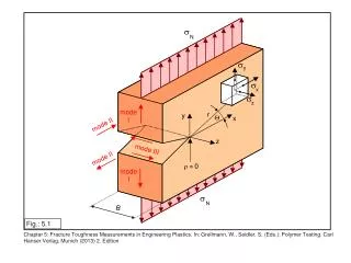
Fig 5.1
Fig 5.1. Refraction at a Surface. Fig 5.6. Spherical Aberration and Paraxial Approximation. Week2-spherical_aberration.avi. NOTE: R>0 if the REFRACTED beam through that surface is on the SAME SIDE as the radius of curvature for that surface.
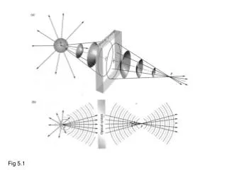

Fig 5.1
E N D
Presentation Transcript
Refraction at a Surface Fig 5.6
Spherical Aberration and Paraxial Approximation Week2-spherical_aberration.avi
NOTE: R>0 if the REFRACTED beam through that surface is on the SAME SIDE as the radius of curvature for that surface. R<0 if the REFRACTED beam through that surface is on the OPPOSITE side of the radius of curvature for that surface
Sign conventions for lens formulas INCOMING light to optic defines the POSITIVE side for sign convention for So OUTGOING light from optic defines the POSITIVE side for sign convention of Si f>0 represents a CONVERGING lens f<0 represents a DIVERGING lens Table 5.2
Ray Tracing/ Magnification Converging Lens/ Diverging Lens http://www.phys.hawaii.edu/~teb/java/ntnujava/Lens/lens_e.html
Longitudinal versus Transverse Magnification Image distorted since magnification in axial direction not same as transverse direction
Fiber Optics Link for animation of total internal reflection http://www.phy.ntnu.edu.tw/ntnujava/index.php?topic=49 Another link for animation of total internal reflection http://www.phy.ntnu.edu.tw/ntnujava/index.php?topic=16
Endoscopy Cartoon of image of blood vessel on end of fiber optic bundle Imaging quality determined by • Amount of light coupled into fibers • Size of fibers
Stomach Images and Colon Polyps Stomach Colon Polyps
Fiber Communications Different Modes travel at different effective speeds through a fiber
Intermodal Dispersion ‘spreads out’ digital optical pulses in a fiber