Download

1 / 22
220 likes | 369 Views
AN INTRODUCTION TO THE BTS-1000 (BERD DAWG) COMMUNICATIONS TEST SET. SLIDE 1 OF 22. This presentation is designed to give you an overview of all the keys, buttons, displays and other gadgets on the front panel of the Digital Interface in your BTS-1000 Test Set.

E N D
AN INTRODUCTION TO THE BTS-1000 (BERD DAWG) COMMUNICATIONS TEST SET SLIDE 1 OF 22
This presentation is designed to give you an overview of all the keys, buttons, displays and other gadgets on the front panel of the Digital Interface in your BTS-1000 Test Set. Please refer to your USER’S MANUAL for more information about any of the functions discussed here. If you have any questions, please feel free to contact us at your convenience at don.brehm@itcmail.net, or 402-498-8400. TO VIEW THIS PRESENTATION, USING PowerPoint, SELECT [View] AND [Slide Show]. USE YOUR COMPUTER [PAGE UP] OR [PAGE DOWN] KEYS, OR CLICK ANYWHERE ON THE SLIDE TO ADVANCE. THE [HOME] KEY WILL TAKE YOU TO THE FIRST SLIDE. THE [END] KEY WILL TAKE YOU TO THE LAST SLIDE. TO REVIEW WHAT YOU’VE DONE, SELECT THE KEY YOU’D LIKE TO SEE AGAIN: MAIN SCREENMAIN MENUDisplay Function, Selection, TextTitle, Screen #, Side # Circuit Status Lines RSD232 & DDS Ports OPTION CONTROL (Key Pad)Jack Field DS1 RCV/XMT KeysFUNCTION KeysAUX ACCESS Jacks HELP Key NEXT Key PREV Key HOME Key SLIDE 2 OF 22
BTS1000 (BERD DAWG) Interface AUX ACCESS DS0 DATA VOLUME VF ACCESS ABC DEF STP RCV XMT E&M 1 2 3 A DS1 ACCESS GHI JKL MNO ST2P SIDE 1 4 5 6 B RS-232 (DCE) RCV XMT PRS TUV WXY ST3P 7 8 9 C SIDE 2 KP * ST POWER Starts the whole thing! -Turns on power -Starts self diagnostics D DSX-MON 0 # BRIDGED POWER Starts the whole thing! -Turns on power -Starts self diagnostics CANCEL ENTER TERM OFF ON RCV1 RCV2 F1 F2 F3 F4 F5 F6 HELP NEXT PREV HOME POWER SLIDE 3 OF 22
BTS1000 (BERD DAWG) Interface AUX ACCESS MAIN SCREEN This screen or your Corporate Logo will appear at Power-ON, after the test set has run it’s self diagnostics. Press any F key to go to the MAIN MENU. DS0 DATA VOLUME VF ACCESS ABC DEF STP RCV XMT E&M 1 2 3 A DS1 ACCESS GHI JKL MNO ST2P SIDE 1 4 5 6 B RS-232 (DCE) RCV XMT PRS TUV WXY ST3P 7 8 9 C SIDE 2 KP * ST D DSX-MON 0 # BRIDGED CANCEL ENTER TERM OFF ON RCV1 RCV2 F1 F2 F3 F4 F5 F6 HELP NEXT PREV HOME POWER SLIDE 4 OF 22
BTS1000 (BERD DAWG) Interface MAIN MENU All tests start at the MAIN MENU. Press HELP here to view calibration dates, options installed, software version and the Serial Number for this test set. AUX ACCESS DS0 DATA VOLUME VF ACCESS ABC DEF STP RCV XMT E&M 1 2 3 A DS1 ACCESS GHI JKL MNO ST2P SIDE 1 4 5 6 B RS-232 (DCE) RCV XMT PRS TUV WXY ST3P 7 8 9 C SIDE 2 KP * ST D DSX-MON 0 # BRIDGED CANCEL ENTER TERM OFF ON RCV1 RCV2 F1 F2 F3 F4 F5 F6 HELP NEXT PREV HOME POWER SLIDE 5 OF 22
BTS1000 (BERD DAWG) Interface DISPLAY SCREEN Shows set up options and status, and results of tests. Move to the next slide for more information about this screen. AUX ACCESS DS0 DATA VOLUME VF ACCESS ABC DEF STP RCV XMT E&M 1 2 3 A DS1 ACCESS GHI JKL MNO ST2P SIDE 1 4 5 6 B RS-232 (DCE) RCV XMT PRS TUV WXY ST3P 7 8 9 C SIDE 2 KP * ST D DSX-MON 0 # BRIDGED CANCEL ENTER TERM OFF ON RCV1 RCV2 F1 F2 F3 F4 F5 F6 HELP NEXT PREV HOME POWER SLIDE 6 OF 22
BTS-1000 MAIN DISPLAY SCREEN Selection text follows to the right of each key. When a selection is made with the function key, a box is drawn around the selection. FUNCTION KEYS These are Menu selection key indicators. When these keys are displayed with boxes around them they are functional, regardless of screen type (SET-UP, RESULT or CONFIGuration) and the displayed location of the keys, the operation is as defined in the HELP screen text. SLIDE 7 OF 22
BTS-1000 MAIN DISPLAY SCREEN SIDE NUMBER The SIDE NUMBER refers to DS1 RCV1 or DS1 RCV2. If SIDE ONE is showing, selections and test results are related to the DS1 RCV1 input. SCREEN NUMBER This number allows the user to track the selected screen’s position within the total number of SETUP or RESULT screens. SETUP screens always precede RESULT screens. Use the NEXT [NXT] and PREVious [PRV] keys to select the next or previous screen. TITLE The text that appears in the title location always refers to the Main Menu selection and if this is a SET-UP, RESULT, or CONFIGuration screen. SLIDE 8 OF 22
BTS-1000 MAIN DISPLAY SCREEN CIRCUIT STATUS LINE This line appears on all screens that relate to DS1 and DSØ testing. The line is divided with SIDE 1 information on the left and SIDE 2 information on the right. The information contained in the Status Line is a blend of MENU SELECTIONS, CIRCUIT ALARM CONDITIONS, CIRCUIT ERROR CONDITIONS and CURRENT CIRCUIT OPERATIONAL STATUS. SIDE 1 Information See next two slides. SIDE 2 Information See next two slides. SLIDE 9 OF 22
BTS-1000 MAIN DISPLAY SCREEN FRAME FORMAT Selectable - SF, ESF or AUTO LINE CODE Selectable - AUTO, AMI, B8ZS SLIDE 10 OF 22
BTS-1000 MAIN DISPLAY SCREEN CIRCUIT STATUS The letters FRM indicate that the circuit is framed and operational. All other indications such as LOS, AIS, RED, YEL are indications of a circuit that is not fully operational. ALARM & ERROR STATUS When any of these DS1 circuit alarms occur (LOS, AIS, LOF, RAI) a flashing A will appear. When any of these DS1 circuit errors occur (BPV, EXZ, FE, SLIP, B8ZS, CRC-6) a flashing E will appear. SLIDE 11 OF 22
BTS1000 (BERD DAWG) Interface DDS PORT This 9 PIN connector is used to connect various DDS test sets and other protocol analyzers. This is an input (TTL) and output port. AUX ACCESS DS0 DATA VOLUME VF ACCESS ABC DEF STP RCV XMT E&M 1 2 3 A DS1 ACCESS GHI JKL MNO ST2P SIDE 1 4 5 6 B RS-232 (DCE) RCV XMT PRS TUV WXY ST3P 7 8 9 C SIDE 2 KP * ST D DSX-MON 0 # BRIDGED CANCEL ENTER TERM OFF ON RS232C (DCE) This port is set up as a DCE Modem connector, which enables the Digital Option Package to connect directly to a DTE device such as a computer, printer or remote control terminal. RCV1 RCV2 F1 F2 F3 F4 F5 F6 HELP NEXT PREV HOME POWER SLIDE 12 OF 22
BTS1000 (BERD DAWG) Interface AUX ACCESS OPTION CONTROL (KEY PAD) The 4 x 4 key pad is used to enter dial digits, select stored tests, select or cancel choices from a CONFIGuration screen, and other functions being developed. DS0 DATA VOLUME VF ACCESS ABC DEF STP RCV XMT E&M 1 2 3 A DS1 ACCESS GHI JKL MNO ST2P SIDE 1 4 5 6 B RS-232 (DCE) RCV XMT PRS TUV WXY ST3P 7 8 9 C SIDE 2 KP * ST D DSX-MON 0 # BRIDGED CANCEL ENTER TERM OFF ON RCV1 RCV2 F1 F2 F3 F4 F5 F6 HELP NEXT PREV HOME POWER SLIDE 13 OF 22
BTS1000 (BERD DAWG) Interface AUX ACCESS DS0 DATA VOLUME VF ACCESS VF ACCESS Jacks The VF ACCESS jacks are for connecting an auxiliary test set to a selected DS0 circuit for further analog or digital tests. ABC DEF STP RCV XMT E&M 1 2 3 A DS1 ACCESS GHI JKL MNO ST2P SIDE 1 4 5 6 B RS-232 (DCE) RCV XMT PRS TUV WXY ST3P 7 8 9 C SIDE 2 KP * ST D DSX-MON 0 # BRIDGED CANCEL ENTER TERM OFF ON RCV1 RCV2 F1 F2 F3 F4 F5 F6 HELP NEXT PREV HOME POWER SLIDE 14 OF 22
BTS1000 (BERD DAWG) Interface AUX ACCESS DS0 DATA VOLUME VF ACCESS ABC DEF STP RCV XMT E&M 1 2 3 A DS1 ACCESS DS1 SIDE 1 & SIDE 2 RCV/XMT Jacks These jacks are used to connect the test set to the circuit under test. The LEDs indicate which jacks are active. GHI JKL MNO ST2P SIDE 1 4 5 6 B RS-232 (DCE) RCV XMT PRS TUV WXY ST3P 7 8 9 C SIDE 2 KP * ST D DSX-MON 0 # BRIDGED CANCEL ENTER TERM OFF ON RCV1 RCV2 F1 F2 F3 F4 F5 F6 HELP NEXT PREV HOME POWER SLIDE 15 OF 22
BTS1000 (BERD DAWG) Interface AUX ACCESS DS1 RCV1/RCV2 Keys These keys are used to select the correct receiver impedance for the selected test location. The impedance selection is indicated by the two LEDs above each key. TERM is selected when the test set terminates the DS1 circuit. The TERM LEDs are lit. BRIDGE is selected if a high impedance input is required. Both LEDs are lit. The BRIDGE mode must access a terminated cable pair for readings to be accurate. This is the POWER ON default mode. MONITOR is used for resistive monitor jack applications. The MON LED will be lit. Note: If the MONITOR jack is not resistor isolated, use the BRIDGED mode. DS0 DATA VOLUME AUXILLIARY ACCESS This location is reserved for future options. VF ACCESS ABC DEF STP RCV XMT E&M 1 2 3 A DS1 ACCESS GHI JKL MNO ST2P SIDE 1 4 5 6 B RS-232 (DCE) RCV XMT PRS TUV WXY ST3P 7 8 9 C SIDE 2 KP * ST D DSX-MON 0 # BRIDGED CANCEL ENTER TERM OFF ON RCV1 RCV2 F1 F2 F3 F4 F5 F6 HELP NEXT PREV HOME POWER SLIDE 16 OF 22
BTS1000 (BERD DAWG) Interface AUX ACCESS FUNCTION Keys F1 - Selects STORED TESTS where available,. F2 - Selects DS1 PERFORMANCE MONITOR tests. F3 - Selects DS1 BERT tests. F4 - Selects DS0 DROP & INSERT tests. F5 - Selects the test set SYSTEM SETUP functions. F6 - Selects other test functions when available. All keys select additional functions within specific tests. DS0 DATA VOLUME VF ACCESS ABC DEF STP RCV XMT E&M 1 2 3 A DS1 ACCESS GHI JKL MNO ST2P SIDE 1 4 5 6 B RS-232 (DCE) RCV XMT PRS TUV WXY ST3P 7 8 9 C SIDE 2 KP * ST D DSX-MON 0 # BRIDGED CANCEL ENTER TERM OFF ON RCV1 RCV2 F1 F2 F3 F4 F5 F6 HELP NEXT PREV HOME POWER SLIDE 17 OF 22
BTS1000 (BERD DAWG) Interface AUX ACCESS HELP Key This key is used to select the built-in user’s manual. The HELP screen displayed will be directly related to the screen that was displayed before entering HELP. The NEXT and PREV keys will access all additional HELP screens related to the screen showing. Use HOME to return to the test screen. DS0 DATA VOLUME VF ACCESS ABC DEF STP RCV XMT E&M 1 2 3 A DS1 ACCESS GHI JKL MNO ST2P SIDE 1 4 5 6 B RS-232 (DCE) RCV XMT PRS TUV WXY ST3P 7 8 9 C SIDE 2 KP * ST D DSX-MON 0 # BRIDGED CANCEL ENTER TERM OFF ON RCV1 RCV2 F1 F2 F3 F4 F5 F6 HELP NEXT PREV HOME POWER SLIDE 18 OF 22
BTS1000 (BERD DAWG) Interface AUX ACCESS NEXT Key This key is used to move to the next screen in the set up, help or test process. DS0 DATA VOLUME VF ACCESS ABC DEF STP RCV XMT E&M 1 2 3 A DS1 ACCESS GHI JKL MNO ST2P SIDE 1 4 5 6 B RS-232 (DCE) RCV XMT PRS TUV WXY ST3P 7 8 9 C SIDE 2 KP * ST D DSX-MON 0 # BRIDGED CANCEL ENTER TERM OFF ON RCV1 RCV2 F1 F2 F3 F4 F5 F6 HELP NEXT PREV HOME POWER SLIDE 19 OF 22
BTS1000 (BERD DAWG) Interface PREV Key This key is used to move to the previous screen viewed in the set up, help or test process. AUX ACCESS DS0 DATA VOLUME VF ACCESS ABC DEF STP RCV XMT E&M 1 2 3 A DS1 ACCESS GHI JKL MNO ST2P SIDE 1 4 5 6 B RS-232 (DCE) RCV XMT PRS TUV WXY ST3P 7 8 9 C SIDE 2 KP * ST D DSX-MON 0 # BRIDGED CANCEL ENTER TERM OFF ON RCV1 RCV2 F1 F2 F3 F4 F5 F6 HELP NEXT PREV HOME POWER SLIDE 20 OF 22
BTS1000 (BERD DAWG) Interface AUX ACCESS HOME Key This key is used to escape from any screen to the Main Menu, or return from a HELP or CONFIGuration screen to the screen that was previously chosen. DS0 DATA VOLUME VF ACCESS ABC DEF STP RCV XMT E&M 1 2 3 A DS1 ACCESS GHI JKL MNO ST2P SIDE 1 4 5 6 B RS-232 (DCE) RCV XMT PRS TUV WXY ST3P 7 8 9 C SIDE 2 KP * ST D DSX-MON 0 # BRIDGED CANCEL ENTER TERM OFF ON RCV1 RCV2 F1 F2 F3 F4 F5 F6 HELP NEXT PREV HOME POWER SLIDE 21 OF 22
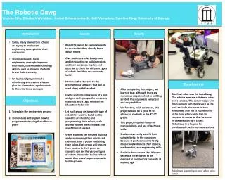
CONGRATULATIONS !!! You made it through this document. That’s a good thing!! Now refer to your manual to set up and run a test. We appreciate you support and your business. If you have any questions please contact us at 402-498-8400 or email - don.brehm@itcmail.net. SLIDE 22 OF 22