Download
1 / 31
310 likes | 396 Views
The picosecond club. A group from Chicago, Argonne and Fermilab are interested in the development of large-area systems to measure the time-of-arrival of relativistic particles with (ultimately) 1 pico-second resolution, and for signals typical of Positron-Emission

E N D
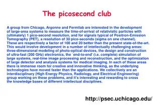
The picosecond club A group from Chicago, Argonne and Fermilab are interested in the development of large-area systems to measure the time-of-arrival of relativistic particles with (ultimately) 1 pico-second resolution, and for signals typical of Positron-Emission Tomography (PET), a resolution of 30 pico-seconds (sigma on one channel). These are respectively a factor of 100 and 20 better than the present state-of-the-art. This would involve development in a number of intellectually challenging areas: three-dimensional modeling of photo-optical devices, the design and construction of ultra-fast (200 GHz) electronics, the `end-to-end' (i.e. complete) simulation of large systems, real-time image processing and reconstruction, and the optimization of large detector and analysis systems for medical imaging. In each of these areas there is immense room for creative and innovative thinking, as the underlying technologies have moved faster than the applications. We collectively are an interdisciplinary (High Energy Physics, Radiology, and Electrical Engineering) group working on these problems, and it's interesting and rewarding to cross the knowledge bases of different intellectual disciplines. http://psec.uchicago.edu/
- 2”x2” Burle/Photonis 85011 1024-anodes 10-micron pore tubes (skew timing over a 2”x2” tube ~100 ps) - Hamamatsu PLP-10 picosec laser
TESTING A SILICON PHOTOMULTIPLIER TIME-OF FLIGHT(TOF) SYSTEM IN FERMILAB’S TEST BEAM FACILITYAnatoly Ronzhin, Mike Albrow, Erik Ramberg – Fermilab,Jerry Vavra – SLAC,Henry Frisch, Tyler Natoli, Camden Eartly, Heejong Kim, Andrew Kobach, Fukun Tang,Scott Wilbur, Jean-Francois Genat – University of Chicago,Ed May, Karen Byrum, John Anderson, Gary Drake – Argonne National Laboratory12 September, 2008
Motivation Reflector Optimization LSO Optimization PMT Optimization Optimization of LSOfor Time-of-Flight PET W. W. Moses1, M. Janecek1, M. A. Spurrier2, P. Szupryczynski2,3 ,W.-S. Choong1, C. L. Melcher2, and M. Andreaco3 1Lawrence Berkeley National Laboratory2University of Tennessee, Knoxville3Siemens Medical Solutions October 21, 2008 Outline: This work was supported by the NIH (NIBIB grant No. R01-EB006085).
500 ps timing resolution 7.5 cm localization D Time-of-Flight in PET c = 30 cm/ns • Can localize source along line of flight. • Time of flight information reduces noise in images. • Variance reduction given by 2D/ct. • 500 ps timing resolution5x reduction in variance! • Time of Flight Provides a Huge Performance Increase! • Largest Improvement in Large Patients
Commercial TOF PET w/ LSO ~550 ps Coincidence Timing Achieved
Our Goal:“Demonstration” TOF PET Camera • With better timing resolution (t), huge gains predicted(23x variance reduction for 100 ps timing) • Measure image improvement vs. timing resolution • Use LSO scintillator • Don’t change other factors that influence SNR(efficiency, scatter fraction, etc.) Achieve the Best Timing Possible w/ LSO
What Limits Timing Resolution? Non-TOF Block Detector Module Baseline 160 ps Crystal Geometry 326 ps Light Sharing 454 ps PMT 422 ps PMT Array 274 ps • Many Factors • “Optical Geometry” Particularly Important
Proposed Side-Coupled Design PMT 384 ps (543 ps coinc.) Conventional Geometry (End-Coupled Crystal) ScintillatorCrystal 218 ps Proposed Geometry(Side-Coupled Crystal) PMT Shorter Optical Path Length & Fewer Reflections
Hole in ReflectorOn Top Face of Crystals Two LSO Crystals (each 6.15 x 6.15 x 25 mm3) Detector Module Design Reflector (on all five faces of each crystal, including the face between the two crystals) PMT (HamamatsuR-9800) Optical Glue (between lower crystal faces and PMT) Two Side-Coupled Scintillator Crystals per PMT
Crystal ofInteraction Detector Ring Geometry • Top face of each crystal (with hole in reflector) is coupled via a small (<1 mm) air gap to the edge of one opposing PMT. • Light seen by the opposing PMT is used to decode the crystal of interaction. Exploded View Crystals Decoded by Opposing PMT
Camera Geometry Section of Detector Ring Lead Shielding Modules • Detector ring is 825 mm diameter, 6.15 mm axial • 192 detector modules, 384 LSO scintillator crystals • Adjustable gap (6 – 150 mm) between lead shields allows “scatter-free” and “3-D” shielding geometries “Real” Single-Ring PET Camera for Humans & Phantoms
Surface & Reflector Optimization Method • 6.15 x 6.15 x 25 mm3 • Reflector on 5 Sides • Optical Grease • No Hole on Top • Measure Timing of “Raw” Crystal(saw cut finish, Teflon tape reflector) • Apply Surface Treatment • Apply Reflector • Re-Measure Timing • Compute Percent Change • Repeat for 5 Crystals & Average Results • Do for All Surface / Reflector Combinations(>100 crystals, each measured twice) R-9800 Same PMT forall measurements Measure PercentageChange in Timing
Average 1.00 1.02 1.01 0.99 1.00 1.00 0.98 Average 1.01 0.96 1.03 Surface & Reflector Results Reflector Saw Cut Chemically Mechanically Etched Polished Air Gap Teflon 1.00 ± 0.17 0.94 ± 0.10 1.06 ± 0.09 ESR 1.01 ± 0.08 0.96 ± 0.16 1.08 ± 0.08 Lumirror 1.03 ± 0.13 0.96 ± 0.06 1.04 ± 0.12 Glued ESR 0.99 ± 0.09 0.98 ± 0.03 1.01 ± 0.18 Lumirror 1.04 ± 0.10 0.97 ± 0.10 0.98 ± 0.22 Melinex 1.01 ± 0.16 0.99 ± 0.06 1.01 ± 0.20 Epoxy 1.00 ± 0.16 0.95 ± 0.09 1.00 ± 0.15 Paint 0.96 ± 0.03
Optimization: LSO Composition I0 I(t) = I0 exp(-t/) Light Output = I0 • Both Scintillators Have Same Light Output (photons/MeV) • Red Decay Time is 2x Longer Than Blue Decay Time • Predicted Timing Resolution 1/sqrt(I0) • Want High Total Light Output & Short Decay Time • Possible By Co-Doping LSO With Calcium
High Light Out The Good Stuff! Short 0.1% 0.3% 0.4% 0.2% = Ca-doped Optimization: LSO Composition Normal LSO Ca-Doping Gives High Light Output & Short
0.1% 0.4% 0.3% 0.2% = Ca-doped Measured Results: LSO Composition Normal LSO Scaled by1/sqrt(I0) • Ca-Doping Gives Good Timing Resolution • ~15% Improvement Over Normal LSO
Blue Sensitivity Index Peak QE Optimization: Photomultiplier Tube • Predicted Timing Resolution 1/sqrt(QE) • Want High Quantum Efficiency Version of PMT
= “32% QE” PMTs Measured Results: High QE PMTs Normal (“28% QE”) PMTs Scaled by1/sqrt(Blue Index) • Increased QE Improves Timing Resolution by 7% • Expect 10% Improvement with 35% SBA PMT
Summary Hardware Single Coinc. TOF(ps fwhm) (ps fwhm) Gain End-Coupled Crystal 384 544 4.3 Side-Coupled Crystal 218 309 7.6 Etched, Reflector Paint 227 321 7.3 Ca-Doped LSO 182 258 9.1 32% QE PMT 155 219 10.6 35% QE “SBA” PMT 148 209 11.1 • TOF PET with Significantly Better Timing is Possible • To Achieve, We Must “Think Outside the Block Detector”
Scintillator Array Thinned SiPM Array Future TOF-PET? (one layer for SPECT) • Depth of Interaction & 150 ps Timing Resolution • 11x Reduction in Variance in Practical Geometry