Download
1 / 41
420 likes | 670 Views
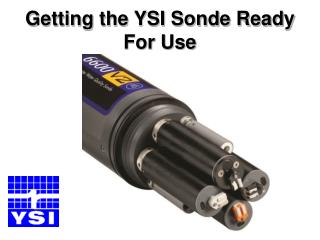
Getting the YSI Sonde Ready For Use. Quality Data Proper Maintenance & Calibration. Keep all electrical contacts dry Proper removal / installation of probes Good DO membrane installation Use Good Laboratory Practice Proper Rinse method between buffers/standards

E N D
Quality DataProper Maintenance & Calibration • Keep all electrical contacts dry • Proper removal / installation of probes • Good DO membrane installation • Use Good Laboratory Practice • Proper Rinse method between buffers/standards • Pre-rinse…using small amount of calibration solution • Allowing time for Equilibration • Quality Calibration • Understanding Sensor Diagnostics
4 3 5 Probe Installation/RemovalReview Handout DISSOLVED OXYGEN ISE 4 ISE 3 CHLOROPHYLL TURBIDITY T C ISE1 / ISE2 (pH / ORP) COND/TEMP ISE 5
Reconditioning DO Probe for Maintenance and/or High DO Charge • Remove membrane, rinse probe in clean water, and dry off probe surface • Use the YSI 6035 kit to service electrodes (note that the sanding disc must be stroke parallel with the electrodes) (Care & Maintenance Section) • Rinse probe surface area with clean water and wipe away residue • Re-membrane probe and check DO Charge (after 5 minutes of probe burn-in). NOTE: Install new O-RING • If reconditioning DO Probe does not reduce High Charge, repeat conditioning. If it does not help, then replace probe or contact Technical Support at YSI for further assistance.
2 Dirty Anodes 1 Dirty Anode Serviced Probe DO Probe Service
Membrane Installation / Quality DataPrepare the Probe with KCl
Temperature No calibration or service available But check accuracy with a Precision Certified Thermometer
Conductivity Service and Calibration • Always service conductivity cell before calibration (Care and Maintenance Section) • Always use a standard that is a 1000 uS/cm or greater • Pre-rinse before calibration • Always use fresh standards, and allow time to equilibrate • Ensure that conductivity cell is totally submerged in solution and lightly shake sonde to remove any air bubbles • Never accept an “Out of Range”
Conductivity Calibration Precautions & Diagnostics • Calibrate in SpCond (Specific Conductance) • Enter correct value e.g.: 1000 uS/cm Calibration value has to be entered as a mS/cm) 1000 uS/cm = 1 mS/cm • After calibration “ALWAYS” check “AND” record Cell Constant in “Advanced / Cal Constants Menu” Range 5.0 ± 0.5 (should be very close with each cal.) • If Cell Constant is out of range clean and recalibrate • SEE CALIBRATION WORK SHEET
pH/ORP Maintenance Tips • During calibration; if mV readings are out of specs, or if there is slow response, do cleaning procedure to probe (Care and Maintenance Section) • Soak probe for 24 - 48 hrs. in 2M KCl note:Proper Storage will extend the life of the probe • If all this fails, replace electrode (Reference first)
Clean pH Probe Dirty pH/ORP Probe pH Probe Service
pH / ORP Diagnostics and Calibration • In “Report Menu” enable pH mV • Place into a pH 7.0 buffer, let Equilibrate and record mV value. Considered acceptable range: 0 +/- 50 ?? • 4.0 buffer should be +177 (from 7 buffer mV value) range 165 to 180 mV • 10.0 buffer should be -177 (from 7 buffer mV value) range -165 to -180 mV
pH • The potential is related to the pH by a form of the Nernst Equation pH 4.0 +177 mV pH 7.0 0 mV pH 10.0 -177 mV
pH Calibration Tips • Calibrate using at least a 2 Point Cal. (7 buffer always being the first point) • Make sure Temperature Probe is in the pH Buffer and allowing time for Equilibration • Pre-rinse between buffers • Record mV values in all buffers and check probe response between buffers • Never accept an “Out of Range” • SEE CALIBRATION WORK SHEET
ORP / REDOX Calibration CALIBRATION CHART Temperature CelsiusZobell Solution Value, MV -5 270.0 0 263.5 5 257.0 10 250.5 15 244.0 20 237.5 25 231.0 30 224.5 35 218.0 40 211.5 45 205.0 50 198.5 NOTE:All ISE sensors, requires the pH and temperature probe to be in solution during calibration. • Never accept an “Out of Range” • SEE CALIBRATION WORK SHEET
Depth Sensor Maintenance • Use syringe from Maintenance Kit; this is the only tool to be used on the depth sensor • If further cleaning is required, soak in warm soapy tap water, then try syringe again
Depth Sensor Calibration • Calibrate in air to zero • For more accurate reading in reference to WQ sensors; apply offset to calibration • Never accept an “Out of Range” • SEE CALIBRATION WORK SHEET
DO Sensor Diagnostics • In Report menu; Enable DO Charge confirm that DO charge is 50 +/- 25, if out of specs recondition probe • Put into RUN MODE for 15 - 20 minutes before calibration(Probe Burn In) • Confirm DO Warm-up Pattern(PROBE HAS TO BE COLD BEFORE STARTING THIS TEST) • Check DO Gain “Advance/Cal Const. Menu” (After Calibration) should be 1 within a range of .7 to 1.5
Dissolved Oxygen Calibration • Calibrate with probe coldOR fully warmed up?? (RS232 auto sleep enabled) ; UNATTENDED (RS232 auto sleep disabled) ; SPOT SAMPLING • Membrane and temperature sensor must be dry • Probe must be in a water saturated air, or air saturated water • Enter current barometer reading (mm/Hg) • Never accept an “Out of Range” • SEE CALIBRATION WORK SHEET
Optic Probes Service and Calibration • Turbidity • Chlorophyll • Rhodamine • BGA-PC…Fresh to Brackish Water • BGA-PE…Brackish to Marine Water • DO
Optic Probe Wiper Wiper Motor Wiper Sponge Wiper
Turbidity Probe test and Calibration • Finger Test to confirm probe response and wiper parking • Calibration process more critical in certain applications: (review handout) • Standards to use / value to enter (review handout) • For 6600EDS Sonde; remove brush and install clean wiper block with clean pad
Chlorophyll, Rhodamine and BGA Calibration • Accept default calibration and use for screening and/or monitoring trends • Check for drift and/or slightly enhance accuracy using dye solution to simulate field data • Use extractive analysis results from field samples to post calibrate all readings (Chlorophyll, BGA)
Calibration of Optical DO • Calibration method the same as for Rapid Pulse, e.g. air saturated water / water saturated air, entering correct barometric pressure value, etc. (RS232 can be enabled for either application) • Can do a 2 point calibration; 1st. Point being in zero oxygen environment; 2nd. Point in saturated environment • Diagnostics is DO gain; acceptable range is .75 to 1.25
Membrane Removal The wiper set screw is loosened with the Allen tool provided, then the wiper is removed.
Membrane Removal The membrane can now be removed. The three membrane screws are removed using the Allen tool provided.
Membrane Replacement • Remove the new sensor membrane assembly from its hydrated container and dry the underside completely. Ensure both sides of the membrane cavity are dry. • Be sure to enter the new calibration code values into sonde menu. Topside Underside
Final test of all Sensors after Calibration • Place sensors in tap water (aerated for 20 minutes or more) • Check for response time to stabilize on all sensors (this will vary from sensor to sensor), and look for realistic values • Review handout on pH response test
REVIEW • CALIBRATION WORK SHEET • “GLP” FILE • TRANSPORT METHODS OF SONDE
Sensor Storage Recommendations • “General Rule” • Short term (4 weeks or less): Saturated Air • Long term (Seasonal): Varies with Sonde Model 2. Sonde Care and Maintenance Review Handout