Download
1 / 20
230 likes | 663 Views
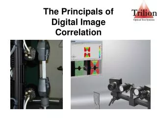
The Principals of Digital Image Correlation. Motivation. Problem: Static / dynamic measurement Position Dynamic displacement Dynamic deformation Speed / velocity Acceleration Strain. Previous Solution :. Displacement Sensors Laser trackers LVDT Draw Wire Sensors Accelerometers

E N D
Motivation Problem: Static / dynamic measurement Position Dynamic displacement Dynamic deformation Speed / velocity Acceleration Strain Previous Solution: • Displacement Sensors • Laser trackers • LVDT • Draw Wire Sensors • Accelerometers • Strain Gages • Extensometers • Clip gages • Profilometer • LVDT
Motivation Collecting data at a single point Setup (Displacement Sensor): • Reference Frame • Mounting the Sensor • Wire up Sensor • Data Acquisition • Data Analysis Displacement Sensor Reference Data Acquisition
Motivation Collecting data at several points Reference Setup (Displacement Sensor): • Reference Frame • Mounting the Sensor • Wire up Sensor • Data Acquisition • Data Analysis Reference Reference Reference Data Acquisition Reference Reference Still only 1D
Motivation Industry requires comprehensive analysis tools Imagine a 3D setup
Motivation Design Criteria Measure & Visualize Entire Structure’s Responseincluding: • 3D displacements & strain gradients • including complex material types & geometries
Motivation • Design Criteria Verify Finite Element Models with 10,000+ measurement points Reduce the Number of Required Prototypes ($$$)
DIC Overview DIC is a powerful method for detecting deformation on the surface of a material or component and is most commonly used in applications that involve: • Materials testing and Characterization • Failure and Fatigue Studies • Long Term Health Monitoring • Materials that have a complex composition or shape • Static and Dynamic Measurements of Strain or Motion
DIC Overview Theory • - Digital Image Correlation (DIC) systems use the principals of photogrammetry, digital image processing, and in most cases stereo imaging to track features in space and assign their position to a predetermined coordinate system • - The measurement is made by the comparison of an image series that is captured over timescales from microseconds to years • - 2D measurements (in-plane) and 3D measurements (in and out of plane) are possible • - Analysis is done in post-processing
DIC Overview Theory • - Much like a strain gage is zeroed to a condition that is said to be “undeformed” and then used as reference for future deformations the first image taken by DIC is used as the undeformed reference condition. • - DIC is a non-contact optical measurement system that measures surface displacements of an object subjected to a driving force • - Provides experimental data that is directly comparable to Finite Element simulations • - Triangulation between the stereo camera pair is used to determine location in z-direction (out of plane)
DIC Overview • Advantages: • Non-Contact Measurement • Rich data set compiled from over 10,000 pts on the surface • Analysis is done in post-proccessing (place gages on after test) • Provides information for shape, position, displacement, and strain • Calibration Technique ensures high accuracy • Not affected by rigid body motion Disadvantages: • Cannot Measure Existing Damage • Must have clear line of sight to part by both cameras
DIC Hardware TodayCameras • High Resolution CCD Cameras (no internal moving parts) 2MP – 12MP • Larger Sensors than point and shoot cameras provide better pixel quality with less pixels • High Light Sensitivity • Typically Monochrome (Black and White) • Capable of Image Acquisition Rates from 15Hz to 1M fps
DIC Hardware TodaySensor Controller and Computer • Data Acquisition Controller that triggers cameras to take pictures • Synchronizes with Test machines and records analog-to-digital signals • Load, and Displacement • Temperature • Uploads images and AD information to computer
DIC Hardware TodayCalibration Artifacts • Provide Scale information for the field of view and used to create a calibrated volume within which the 3D coordinates are known • Calibration Objects have a dense grid of points on them which are at a known location by sensor supplying in-plane coordinate information • By moving the calibration object closer or further from the camera, information can be provided to the sensor relating depth of field and out of plane coordinates
Using Photogrammetry To track a single point The center point of an ellipse or a target can be tracking in calibrated space by interpolating to find its location The perimeter of the ellipse where the color changes from black to white is traced by some n number of pixels The more pixels that trace the ellipse the more accurate its location can be tracked Sub Pixel Interpolation
DIC ProcedureUsing Facets to create 3D coordinates from a 2D image R L R L Undeformed Specimen L R L R Deformed Specimen • Image acquisition by stereo camera pair • Speckle Pattern on the specimen tracked in both camera images by regularly spaced facets as part deforms
DIC Procedure 3D Results • Image processing • 3D coordinates • 3D displacements • and velocity • Strain tensor • Major and Minor strain • Strain in X, Y, shear strain • Thickness reduction • Strain rates for all strain values
DIC ProcedureSensitivity • Displacement Sensitivity out of plane is 1/30,000 the field of view regardless of camera resolution • In Plane sensitivity is 10x higher and increases with resolution • Field of ViewDisplacement Sensitivity • 10 x 8 mm 0.3 Microns • 100 x 80 mm 3.0 Microns • 1 Meter x 800 mm 30.0 Microns • Strain Sensitivity is Constant; 50-100 Microstrain but resolution for strains increase as field of view decreases (pixel scaling factor) Noise Floor for 135mm FOV is 0.16 Microns. Total Displacement of 0.6 Microns is Clearly Visible
Thank you for your attention Trilion Quality Systems 500 Davis Drive, Suite 200, Plymouth Meeting, PA 19462 Office: (215) 710-3000 Fax: (215) 710-3001 Email: Info@Trilion.com Web Site: www.Trilion.com www.Trilion.com