Biomagnetic Field Generation
340 likes | 651 Views
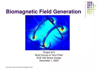
Biomagnetic Field Generation. Project #10 Brett Duncan & Tanvi Patel ECE 445 Senior Design December 1, 2005 http://www.comsol.com/showroom/gallery/15.php. Introduction. Biomagnetics – the study of applied magnetic fields on living tissue.

Biomagnetic Field Generation
E N D
Presentation Transcript
Biomagnetic Field Generation Project #10 Brett Duncan & Tanvi Patel ECE 445 Senior Design December 1, 2005 http://www.comsol.com/showroom/gallery/15.php
Introduction • Biomagnetics – the study of applied magnetic fields on living tissue. • Design and implement a biological research device which allows for the application of magnetic fields to cell culture chambers
Relevance • Allow for the application of magnetic field to cell cultures (normal, cancer cells) to determine the magnetic field effects on cell growth, differentiation and repair. • Magnetic fields are being used along with iron-containing antibodies as an alternative to Flow Cytometry for cell sorting and identification.
Objectives • The overall goal is to create a reliable and accurate device which can provide a uniform magnetic field throughout a specified volume over a culture dish. • Also, to characterize this field in a way that will be useful for studies of cell cultures placed inside the magnetic field.
Features • Magnetic Field range between 1 and 100 Gauss with a resolution of one Gauss. • User friendly display showing current field strength. • Quick and easy ability to “dial in” desired magnetic field. • Adaptable to different sized cell culture containers.
Device Overview • Agilent 25 Watt Power Supply - Provide + 5 Volt for PIC and LCD • Xantrex 1000 Watt Power Supply - Provide 14 Volt and 0 – 7.2 Amps to Buck Converter and Magnetic Chamber
Buck Converter • Allows for tunable current supplied to Magnetic Chamber for control over magnetic field strength
Magnetic Field Chamber • Generates magnetic field for application to a variety of cell culture containers
PIC Microcontroller/LCD • PIC Microcontroller - Receives reference voltage as an input and uses a stored calibration equation to calculate magnetic field in chamber • LCD Display - Displays calculated magnetic field from PIC for the user
Power Supply Noise Testing • Vmax = 14.438 V • Vmin = 13.578 V • Max Ripple: 850 mV
Noise Effects on Device Performance Top Left : Agilent Power Supply Top Right : Xantrex Power Supply Bottom Left : Xantrex Power Supply after noise reduction
Device Testing • Determination of maximum field strength and an optimum usable range for the device • Set device at 100% duty cycle and increased supply voltage while monitoring magnetic field strength and state of components
Field Strength and Resolution Testing • Maximum field strength of 177 Gauss • Determined a usable range of 0 to 100 Gauss with a resolution of one Gauss
Magnetic Field Strength vs. Current Measurement • Vary the duty cycle of the Buck Converter to determine field strength vs. current • Compare results versus theoretical calculation N
Calibration Curve • Varying the duty cycle corresponds with: • A change in Magnetic Field Strength • A change in current through the sensing resistor • This results in a change in voltage across the resistor • Therefore a voltage across the sensing resistor can be related to a field strength • A calibration curve was established using these 2 parameters
Magnetic Field Characterization • An x,y,z,coordinate system was defined • 10 x 16 cm stage area • 4 cm above and below stage • Measurements of Magnetic field strength were taken throughout the stage area in two cm intervals
Successes • Usable range of 0-100 Gauss Magnetic Field with 1 Gauss resolution • Uniform Magnetic Field of 30 cm3 • Magnetic Field Strength Displayed within 1.8% accuracy of exterior magnetometer
Challenges • Linear Amplifier circuit unable to handle large power dissipation • Power dissipation considerations with components, heatsinks, and wiring • Limitations due to high currents • Magnetic Chamber Construction • Mathematical limitations with PIC
Recommendations • Current Design • Use of a PIC with advanced math functions • Less noisy power supply • Use of Custom printed circuit boards
Recommendations • To achieve 1000 Gauss field • Power Dissipation Considerations • Minimize MOSFET RDS(on) • Minimize Diode Vf • Larger heatsinks, cooling fans • Magnetic Chamber Design • Switch to magnetic wire • Increase wire size • Cooling for coils
Summary • We successfully created a variable magnetic chamber for biological research • Applicability determined by research demands for • Cancer research • Normal cell healing and growth • Cell sorting and identification
Credits • Professor Ray Fish • Professor Jonathan Kimball