Download
1 / 31
310 likes | 646 Views
MSP430 Mixed Signal Microcontroller – Parte 2. Afonso Ferreira Miguel Source: slau056d – Texas instruments. Interrupts. There are three types of interrupts: System reset (Non)-maskable NMI Maskable. Maskable Interrupts.

E N D
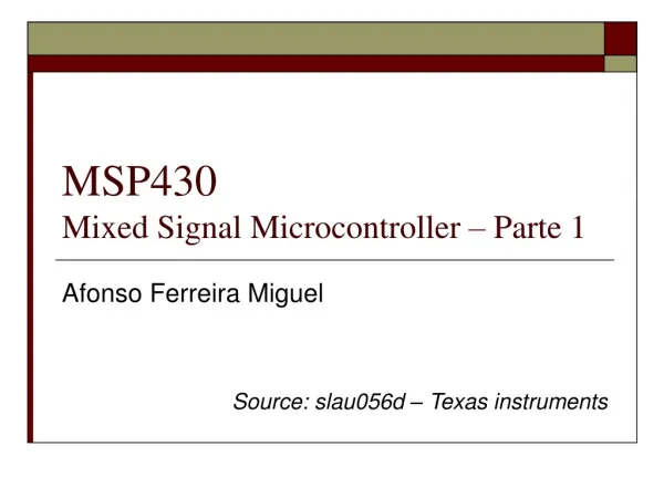
MSP430Mixed Signal Microcontroller – Parte 2 Afonso Ferreira Miguel Source: slau056d – Texas instruments
Interrupts • There are three types of interrupts: • System reset • (Non)-maskable NMI • Maskable
Maskable Interrupts • Maskable interrupts are caused by peripherals with interrupt capability including the watchdog timer overflow in interval-timer mode. • Each maskable interrupt source can be disabled individually by an interrupt enable bit, or • all maskable interrupts can be disabled by the general interrupt enable (GIE) bit in the status register (SR).
Maskable Interrupts • Interrupt Acceptance • Any currently executing instruction is completed. • The PC, which points to the next instruction, is pushed onto the stack. • The SR is pushed onto the stack. • The interrupt with the highest priority is selected if multiple interrupts occurred during the last instruction and are pending for service. • The interrupt request flag resets automatically on single-source flags. Multiple source flags remain set for servicing by software. • The SR is cleared with the exception of SCG0, which is left unchanged. This terminates any low-power mode. Because the GIE bit is cleared, further interrupts are disabled. • The content of the interrupt vector is loaded into the PC: the program continues with the interrupt service routine at that address.
Maskable Interrupts • Interrupt Acceptance
Maskable Interrupts • Return From Interrupt • The interrupt handling routine terminates with the instruction: RETI (return from an interrupt service routine) • The return from the interrupt execute the following actions: • The SR with all previous settings pops from the stack. All previous settings of GIE, CPUOFF, etc. are now in effect, regardless of the settings used during the interrupt service routine. • The PC pops from the stack and begins execution at the point where it was interrupted.
Maskable Interrupts • Return From Interrupt • Interrupt nesting is enabled if the GIE bit is set inside an interrupt service routine. When interrupt nesting is enabled, any interrupt occurring during an interrupt service routine will interrupt the routine, regardless of the interrupt priorities.
MSP430F449 - Interrupt Vector • Interrupts in ASM
MSP430F449 - Interrupt Vector • Interrupts in C
MSP430F449 - Interrupt Vector • Interrupts in C++ Interrupção definida no arquivo msp430x44x.h
FLL+Clock Module • The frequency-locked loop (FLL+) clock module supports low system cost and ultralow-power consumption. • Using three internal clock signals, the user can select the best balance of performance and low power consumption.
FLL+Clock Module • LFXT1CLK: Low-frequency/high-frequency oscillator that can be used either with low-frequency 32768-Hz watch crystals, or standard crystals, resonators, or external clock sources in 450-kHz to 8-MHz range. • XT2CLK: Optional high-frequency oscillator that can be used with standard crystals, resonators, or external clock sources in the 450-kHz to 8-MHz range. • DCOCLK: Internal digitally controlled oscillator (DCO) with RC-type characteristics, stabilized by the FLL. • Four clock signals are available from the FLL+ module: • ACLK: Auxiliary clock. The ACLK is the LFXT1CLK clock source. ACLK is software selectable for individual peripheral modules. • ACLK/n: Buffered output of the ACLK. The ACLK/n is ACLK divided by 1,2,4 or 8 and only used externally. • MCLK: Master clock. MCLK is software selectable as LFXT1CLK, XT2CLK (if available), or DCOCLK. MCLK can be divided by 1, 2, 4, or 8 within the FLL block. MCLK is used by the CPU and system. • SMCLK: Submain clock. SMCLK is software selectable as XT2CLK (if available), or DCOCLK. SMCLK is software selectable for individual peripheral modules.
FLL+Clock Module • After a PUC, MCLK and SMCLK are sourced from DCOCLK at 32 times the ACLK frequency. When a 32,768-Hz crystal is used for ACLK, MCLK and SMCLK will stabilize to 1.048576 MHz.
Timer A • Timer_A is a 16-bit timer/counter with three or five capture/compare registers. • Timer_A can support multiple capture/compares, PWM outputs, and interval timing. Timer_A also has extensive interrupt capabilities. • Interrupts may be generated from the counter on overflow conditions and from each of the capture/compare registers.
Timer A • Timer_A features include: • Asynchronous 16-bit timer/counter with four operating modes • Selectable and configurable clock source • Three or five configurable capture/compare registers • Configurable outputs with PWM capability • Asynchronous input and output latching • Interrupt vector register for fast decoding of all Timer_A interrupts
Timer A • The 16-bit timer/counter register, TAR, increments or decrements (depending on mode of operation) with each rising edge of the clock signal. • TAR can be read or written with software. Additionally, the timer can generate an interrupt when it overflows. • TAR may be cleared by setting the TACLR bit. • Setting TACLR also clears the clock divider and count direction for up/down mode.
Timer A • Timer Modes
Timer A • Up Mode • The up mode is used if the timer period must be different from 0FFFFh counts. • The timer repeatedly counts up to the value of compare register TACCR0, which defines the period. • The number of timer counts in the period is TACCR0+1. • When the timer value equals TACCR0 the timer restarts counting from zero. If up mode is selected when the timer value is greater than TACCR0, the timer immediately restarts counting from zero.
Timer A • The TACCR0 CCIFG interrupt flag is set when the timer counts to the TACCR0 value. • The TAIFG interrupt flag is set when the timer counts from TACCR0 to zero.
Timer A • Registradores Usados • TACTL: Configuração + flags • TACCR0: Valor limite • TAR: Contador
Timer A • TACTL
Operation Modes • The MSP430 family is designed for ultralow-power applications and uses different operating modes. • The operating modes take into account three different needs: • Ultralow-power • Speed and data throughput • Minimization of individual peripheral current consumption
Operation Modes • The low-power modes 0–4 are configured with the CPUOFF, OSCOFF, SCG0, and SCG1 bits in the SR The advantage of including the CPUOFF, OSCOFF, SCG0, and SCG1 mode-control bits in the status register is that the present operating mode is saved onto the stack during an interrupt service routine.
Entering and Exiting Low-Power Modes • An enabled interrupt event wakes the MSP430 from any of the low-power operating modes. The program flow is: • Enter interrupt service routine: • The PC and SR are stored on the stack. • The CPUOFF, SCG1, and OSCOFF bits are automatically reset. • Options for returning from the interrupt service routine: • The original SR is popped from the stack, restoring the previous operating mode. • The SR bits stored on the stack can be modified within the interrupt service routine returning to a different operating mode when the RETI instruction is executed.
Entering and Exiting Low-Power Modes • Status Register (SR)
Entering and Exiting Low-Power Modes • “msp430x44x.h” defines