Ultrafast Laser Ablation and Plasma Diagnostics
630 likes | 1.52k Views
Ultrafast Laser Ablation and Plasma Diagnostics. Zhiyu Zhang Center for Ultrafast Optical Science Department of Electrical Engineering and Computer Science University of Michigan, Ann Arbor, MI. Outline. Introduction and Motivation

Ultrafast Laser Ablation and Plasma Diagnostics
E N D
Presentation Transcript
Ultrafast Laser Ablation and Plasma Diagnostics Zhiyu Zhang Center for Ultrafast Optical Science Department of Electrical Engineering and Computer Science University of Michigan, Ann Arbor, MI
Outline • Introduction and Motivation • Multi-diagnostic comparison of plasmas by ultrafast laser and nanosecond laser ablation • Multi-pulse ablation • Application of double and multi-pulse ablation: isotope enrichment and clusters formation • Summary
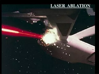
Ultrafast Laser Applications: Materials Processing (I) Above Ablation Threshold • Micromachining: metal, semiconductor, dielectric, dental tissue, 100nm lateral, 10nm vertical; Appl. Phys. A 68 369, Appl. Phys. A 68 403 • DNA transfection; Nature 418 290 • Patterning biomaterials; Appl. Surf. Sci. 208-209 245 • Fresnel zone plate fabrication; Opt. Exp. 10 978 • Surface microstructureing; APL 81 1999 • Photomask repair; J. Vac. Sci. Technol. B 21 204
Ultrafast Laser Applications: Materials Processing (II) Below Ablation Threshold • Waveguide direct writing; Opt. Lett. 21 1729 • Phase transition; JETP Lett. 76 461 • 3D micro-photopolymerization; Nature 412 697 • Nonlinear optical coefficient enhancement; APL 81 1585 • Precipitating nanoparticles inside glasses; APL 81 3040
SnO2 R-cut Al2O3 Ultrafast Laser in Materials Processing
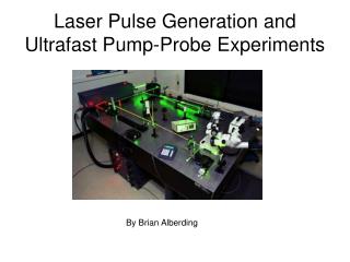
100 fs 100 MHz 2 nJ X 106 0.5 mJ Oscillator Regen Amplifier Nd:YAG 200 mJ Argon 4-pass Amplifier 2-pass Amplifier Compressor 20 mJ 100 fs 10 Hz 100 mJ Nd:YAG Ultrafast Laser System 10 Hz X 10,000 200 ps Beam Splitter Stretcher
Ultrafast Laser System 100 fs 10 Hz 100 mJ
High-Repetition Rate Commercial Ultrafast Laser Laser: 1 kHz, 1 mJ/pulse, 150 fs
Plasma Plume Imaging & Spectroscopy Langmuir Probe • 2” Substrate Holder: • temperature: 77 K to 1000°C • rotation & translation • bias: 0 to -500 V HeNe Electrostatic Analyzer (charge state & energy) Lasers: 10 Hz 780nm 110fs Multi-Target Selector(4 targets with rotation) or Dt Position Detector Vacuum: 10-9 Torr Experimental Setup
MCPs – straight • i/o • Vb • +Vs • Va • - Vs MCPs curved sector • Einzel • lens Electrostatic Energy Analyzer Select ions with E/q=2.254 Vs
Time-of-Flight Spectrum: BN Laser: 100 fs, 780 nm, 50 J/cm2
Time-Resolved OESAl Ablated with 100-fs Pulses • 100 ns Delay Increment • 50 ns Acquisition Window • 100, 780nm, 1J/cm2 Laser Pulses • Continuum Emission at Early Time
Langmuir Probe I-V Curve • Plasma parameters related to the different regions of the I-V curve • Probe theory developed to extract the parameters from the I-V curve • Time-resolved analysis (1ms resolution)
HeNe Probe Laser Deflection Plume Quad Detector Vout HeNe j: Ion or Neutral component Self-similar expansion model for both ion and neutral species C.L. Enloe et al,Rev. Sci. Instrum. 58, 1597 (1987)
Plasma 0 Neutrals HeNe Deflection Signal BN Ablation: 6ns, 18 J/cm2 Parameters: Vion 4.76x106cm/s Vneutral 1.04x106cm/s Nion 5x10¹⁴ Nneutral 1x10¹⁷
In-situ Analysis Plasma Diagnostic Technique • Electrostatic Energy Analyzer • Charge state, Ion energy distribution • Langmuir Probe • Electron temperature, Plasma and floating potential, Density of electrons and ions • Spatial and temporal resolution (1ms) • Optical Emission Spectroscopy • Plasma temperature, Excited states • ns time resolution • Laser Deflection Probe • Ion to neutral ratio • Hydrodynamic component Target: Metal (Al), Nitrides (BN), Oxide (SnO2)
Energy Spectrum of AlEffect of Laser Pulse Width 6 ns,1.06 mm 1.3J/cm2 80 fs, 780 nm 0.4J/cm2 Al Target Ablated in Vacuum
Time-Resolved Electron Temperature: Optical Emission Spectroscopy • Laser Pulses: • 6ns • 1.06mm • 1.4J/cm2 • 100fs • 780nm • 0.4J/cm2
Time-Resolved Electron Temperature: Langmuir Probe 6 ns 80 fs Laser pulses: 80fs 780nm 0.4J/cm2 6ns 1.06mm 1.3J/cm2 Langmuir Probe: 10cm away from Al target
HeNe Deflection: Ion to Neutral Ratio 100 fs Laser Neutral Energy:4 eV Ion Energy: 85eV 6 ns Laser Neutral Energy:4 eV Ion Energy: 100eV
Plume Properties Modified by Laser Pulse • Pulse width: plasma shielding and heating effects • Pulse contrast: enhance the high energy component in the plume (Appl. Surf. Sci 2000) • Pulse intensity: optimum ablation efficiency (MRS 2002) • Multi-Pulse: enhanced ion properties (APL 2003)
Ion Yield and Energy in Ablation Plumes 3.3kJ/cm2 • 10Hz • Ti:Sapphire • Same focus spot • Varying pulse • energy • Ion Energy is converted from TOF signal 0.8kJ/cm2
Laser Wave in Plasma ncr Light Wave in Inhomogeneous Plasma s-pol: Collisional absorption p-pol: Collisional + Resonance absorption Collisional absorption Resonance absorption w ~ laser frequency L ~ plasma scale length v*ie ~ electron-ion collision frequency c ~ speed of light
Modify the Ablation Dynamics by Double Pulse Ablation • Saturation of absorption occurs as single- pulse energy increases due to plasma reflection • Use an appropriately time-delayed secondary laser pulse to add energy into the plasma during the early stages of its expansion. • Examine the effect on the plasma and the clusters
Double pulse experiment • Initial gradient scale length of a plasma Two identical 300fs pulses: tens of ps delay Ref: C. Y. Cote et. al Phy. Rev. E 56, 992 (1997 ) • Thin Film Deposition: reducing particulate CO2 and YAG lasers: 4ns delay Ref: S. Witanachchi, et. al Appl. Phys. Lett. 66 1469 (1995) • X-ray emission Weak pre-pulse, 2ns delay Ref: H. Nakano et. al Appl. Phys. Lett. 79 24 (2001)
Time-of-Flight: Single vs. Double-Pulse Laser: 110fs, 780nm, p-polarized 1x10¹⁶ W/cm2 0~50ps 2x10¹⁶ W/cm2
Double-Pulse Enhanced Optical Emission Laser: 130fs, 780nm, p-pol 1x10¹⁶ W/cm2 0~50ps
Langmuir Probe: Double-Pulse Enhanced Ion Density Laser: 130fs, 780nm, p-pol 1x10¹⁶ W/cm2 0~50ps
Charge State Distribution: Single vs. Double-Pulse Average Charge: Single: 2.5 Double 5-ps: 3.1 Double 10-ps: 3
Ion Yield vs. Laser Intensity (Double-Pulse) Maximum Intensity: 1x10¹⁶ W/cm2
RC M3 M4 BS BS RC RC BS RC 2 M1 M2 4 1 3 Original Beam Path Setup for Generation of 4-pulse Sequence
t1 t1 t3=t2 - t1 t2 Silicon Ablation by Multi-pulse Laser Intensity: 5x10¹⁵ W/cm2 Four-Pulse: t1=5ps, t3 is a variable
Isotopic Enrichment: Double-Pulse Enhancement BN Ablation – 120 fs, 2 x 10¹⁶ W/cm2, Dt = 10 ps Isotope Ratio Ion Yield
Time-resolved Magnetic Field Magnetic field by RA Laser Intensity: 1x10¹⁶ W/cm2 Toroidal magnetic field Laser Intensity: 5x10¹⁸ W/cm2 Borghesi et.al. PRL v81,p112 Sandhu et.al. PRL v89,p225002
Questions • Cluster component in the plume? • Surface roughness is caused by growth effect or clusters formed in plume? • High intensity femtosecond plasma bursts result in dense cluster formation?
Cluster Formation for Cu/NiLaser intensity = 2 x 10¹⁶ W/cm2 ; Tm ~ 1300 C
Cluster Size Distribution: Ni Ni: RT, 10Hz Laser, Single Pulse, 2x10¹⁶W/cm2 Average Size: 242 nm +155nm
Cluster Size Distribution: Ni Ni: RT, 10Hz Laser, Double Pulse, 1x10¹⁶W/cm2, 5ps Delay Average Size: 99nm+41nm
Cluster Size Distribution: Ge Single full-energy pulse
Cluster Size Distribution: Ge Double pulse
Clusters Formation Mechanism (I) • Condensation of ns laser ablation plume • High background pressure, 1 ~ 10 Torr • Hydrodynamic expansion and thermodynamic condensation • Plume nonuniformity gives cluster size distribution • Average size: less than 10 nm
Clusters Formation Mechanism (II) • Photomechenical Effects - fragmentation • Clusters are formed by fragmentation due to the strain associated with gradient of expansion velocity • Cluster size determined by fragmentation time • Average size: less than 10 nm for 1ps fragmentation time
Clusters Formation Mechanism (III) • Photothermal Effects – phase explosion • Superheating leads to homogeneous nucleation • Mixture of vapor and liquid forms clusters • Average size: possible ~100 nm
“Femto-Jet” nozzle Hagena Equation Femtosecond laser ablation: P0: 103 ~104 atm a: small, supersonic expansion Density: very large; k: large for heavy atoms d: jet throat diameter a: jet expansion half angle p0: backing pressure T0: initial gas temperature k: material dependent constant number of atoms per clusters: Nc (G*)2.0~2.5