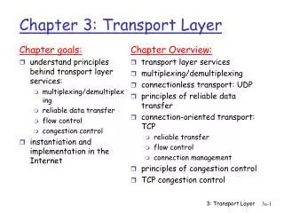
Ch 3. Transport Layer
Myungchul Kim mckim@icu.ac.kr. Ch 3. Transport Layer. Logical communication between application processes running on different hosts A network-layer protocol provides logical communication between hosts.

Ch 3. Transport Layer
E N D
Presentation Transcript
Myungchul Kim mckim@icu.ac.kr Ch 3. Transport Layer
Logical communication between application processes running on different hosts • A network-layer protocol provides logical communication between hosts. • A transport protocol can offer reliable data transfer service to an application even when the underlying network protocol is unreliable. • IP service model: best-effort delivery service • UDP: unregulated
Intermediate routers neither act on, nor recognize, any information that the transport layer may have added to the application messages. • Transport-layer multiplexing: extending host-to-host delivery to process-to-process delivery
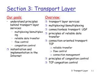
Multiplexing and Demultiplexing • Host-to-host delivery vs process-to-process delivery • Multiplexing • Demultiplexing • Transport-layer multiplexing • Sockets have unique identifiers • Each segment have special fields, port number fields, that indicate the socket to which the segment is to be delivered. • Port number: 16-bit number: from 0 to 65535, well-known port numbers from 0 to 1023. e.g., HTTP (80), FTP(21) • Fig 3.3
A UDP socket is fully identified by a two-tuple consisting of a destination IP address and a destination port number. • Fig 3.4
A TCP socket is identified by a 4-tuple: (source IP address, source port number, destination IP address, destination port number). • In contrast with UDP, two arriving TCP segments with different source IP addresses or source port numbers will be directed to two different sockets. • The HTTP server distinguishes the segments from the different clients by the source IP addresses and source port numbers. • Persistent HTTP vs Nonpersistent HTTP
UDP • Multiplexing and demultiplexing • Light error checking • The application is almost directly talking with IP. • Connectionless • No handshaking • Merits • No connection establishment -> no delay • No connection state • Small packet header overhead: TCP(20), UDP(8 bytes) • Finer application-level control over what data is sent, and when. • How about congestion due to UDP? • New mechanism to force all sources including UDP sources to perform adaptive congestion control. • Applications have built acknowledgements and retransmissions into the applications.
UDP segment structure • Fig 3.7 • UDP checksum • For error detection • UDP at the sender side performs the 1’s complement of the sum of all the 16-bit words in the segment. • At the receiver, all four 16-bit words are added, including the checksum. • If no errors, 111.111. If one of the bits is a zero, then errors. • No recovery from an error.
Principles of Reliable Data Transfer • The transport layer, the link layer and the application layer • Fig 3.8
Reliable data transfer over a Perfectly Reliable Channel: rdt1.0 • Separate FSM • Event/action • Initial state • Fig 3.9 • No difference between a unit of data and a packet • No feedback: reliable channel • No flow control
Reliable data transfer over a Channel: rdt2.0 • Bits in a packet may be corrupted • Positive ack and negative ack • ARQ(Automatic Repeat reQuest) protocols • Capabilities handling the presence of bit errors: • Error detection • Receiver feedback: a 0 value indicate a NAK and a value of 1 could indicate an ACK • Retransmission
Reliable data transfer over a Channel: rdt2.0 • When the receiver is in the wait-for-ACK-or-NAK state, it cannot get more data from the upper layer. • Stop-and-wait protocol • Drawbacks • The ACK or NAK packet could be corrupted. -> checksum • How the protocol should recover from errors in ACK or NAK packets. • A one-bit sequence number: allow the receiver to know whether the sender is sending the previously transmitted packet. • Since we are currently assuming a channel that does not lose packets, ACK and NAK packets do not themselves need to indicate the sequence number of the packet they are acknowledging. • When an out-of-order packet is received, the receiver sends a positive acknowledgement for the packet it has received. -> duplicate ACKs • When a corrupted packet is received, the receiver sends a negative acknowledgement.