Download

1 / 33
330 likes | 462 Views
FACT - First GAPD imaging air shower Cherenkov Telescope – electronics systems. NEC2013 – XXV International Symposium on Nuclear Electronics and Computing 9-16 Sept 2013, Varna, Bulgaria W . Lustermann, ETH Zurich for the FACT collaboration

E N D
FACT - First GAPD imaging air shower Cherenkov Telescope – electronics systems NEC2013 – XXV International Symposium on Nuclear Electronics and Computing 9-16 Sept 2013, Varna, Bulgaria W. Lustermann, ETH Zurich for the FACT collaboration TU Dortmund, ISDC Geneva, University of Geneva, EPFL Lausanne, University of Würzburg, ETH Zurich
Detection > 100 GeV gamma rays Signal amplitude: 200 photons / m2 (1 TeVγ-ray) Spectrum: (300 – 600) nm Duration: few ns Night sky: up to several GHz Optical imaging system (causes losses) Mirror light concentrators photo-detectors Cherenkov spectrum 2.2 km altitude Cut off ~320 nm Showers can as well originate from protons or electrons – requires a selection
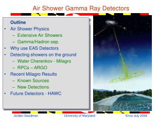
Gamma induced air shower detection • GOAL: detection of gamma induced air showers, measurement of the energy and the source position at the sky • The image parameters including the shower shape, position, photon arrive times allow the reconstruction of energy and source position • Air showers induced by gammas, muons and electrons are short ~few ns • Air showers induced by protons are rather long ~(30 – 100) ns • The lower the detectable light level the lower the energy threshold for photons Operation at high night sky background (~1GHz) and at moon light conditions, should be possible – extending observation time
The Telescope • European Northern Observatory • Roquede los Muchachos, altitude: 2200 m • Canary Island La Palma • Refurbished HEGRA CT3 • Mirror area: 9.5 m2 • New drive system • New counting hut and electrical installation • New camera • G-APDs (SiPMs. …) • Solid light guides • Fully integrated electronics • Using DRS4 • Operational since October 2011 • Monitoring of bright Blazars • Evaluation of stability and performance
Camera features/requirements • Camera • Dim: Length 812 mm, diameter 532 mm, • Weight: ~ 150 kg • 1440 pixels (G-APDs) • FOV: 0.11 deg / pixel (4.5deg total) • Water cooled 4.5 deg • Requirements for the readout electronics: • Dynamic range: ~200 photons / pixel • Resolution: < 0.5 photons (for less than 10 photons) – this will allow to measure the gain of the GAPDs from single photon spectra • Timing resolution ~500 ps • Typical trigger rate of ~50 Hz (~ 350 Hz sustainable trigger rate) • Synchronous trigger distribution ~50ps • Low power consumption • additional electronics: • G-APD bias supply • Low voltage power conversion system • Light monitoring system • Slow control system
Electronics Systems Overview 2 GHz FLV: low voltage conversion FSC slow control (Temp., rel Humidity, voltages) FLP light pulser FDC drive calibration
Photo Detectors (G-APDs) • Easy to use • As good as best PMTs (PDE) • Cheaper than PMTs • Dark counts, cross talk and after pulse are no problem for IACTs • Voltage and Temperature dependence can be kept under control rather easily MPPC glued to solid light concentrator: Increase of the sensitive area Limiting angular (watch only the mirror) Single photon resolution
Electronics Systems Overview 2 GHz FLV: low voltage conversion FSC slow control (Temp., rel Humidity, voltages) FLP light pulser FDC drive calibration
FACT Pre-Amplifier (FPA) • Two different functionalities: • Pre-amplification of signals for later digitization • Summing of signals for the trigger primitives generation • Pre-amplifier • 36 pre-amplifiers channels • Input: AC coupling with npn transistor in base configuration • Input impedance: 25 ohm • Followed by an OPA with gain ~10 • gain: 45 mV / µA • Bandwidth: 200 MHz • Single avalanche signal 2.5 mV at the FAD input of 50 ohm design: U. Roeser, layout: L.Djambazov
Electronics Systems Overview 2 GHz FLV: low voltage conversion FSC slow control (Temp., rel Humidity, voltages) FLP light pulser FDC drive calibration
FACT Digitization (FAD) • DRS4 (Domino Ring Sampler) – PSI (S. Ritt) • Analog switched capacitor array • 9 channels, 1024 time slices per channel • Operated at 2 GHz (500ps / slice) • ROI: 300 slices (150 ns) • Serial readout • Digitization 12 bit ADC running at 20 MHz • FAD board (in total 40) • 36 channels, four DRS4 with input buffers • 2 dual 12bit ADC (AD9238) • Ethernet interface (Wiznet W5300) • FPGA (Xilinx Spartan-3) • Internal PLL of DRS4 used, locked on clock of the trigger master • Relative timing of all channels of all boards to 300ps is possible (requires calibration) • Controllable voltage source for amplitude calibration DRS4 data: permit and require digital signal processing
Arrangement of PCBs FAD’s in one crate are booted in sequence: limit the startup power (required for FPGA booting) Pre-amplifier board (FPA) and analog pipeline ASIC (DRS4) & digitization board (FAD) connected via the mid plane (FMP) distributing power and slow control signals FAD FTU FMP FPA FMP FAD FPA
Electronics Systems Overview 2 GHz FLV: low voltage conversion FSC slow control (Temp., rel Humidity, voltages) FLP light pulser FDC drive calibration
Trigger system (1) • Trigger on analog sums of non overlapping patches: 9 pixel • Functionality spread over several components: FPA – pre-amplifier, FTU – trigger unit and FTM – trigger master • Rate control system (software) maintains a constant trigger rate (70 Hz) under varying conditions • Counter for all discriminator outputs and the majority coincidence output are implemented automatic adjustment of discriminator thresholds stabilize trigger rates under varying conditions
Electronics Systems Overview 2 GHz FLV: low voltage conversion FSC slow control (Temp., rel Humidity, voltages) FLP light pulser FDC drive calibration
Trigger system – Trigger master Note: the trigger part of the VHDL code was purchased from a company
Electronics Systems Overview 2 GHz FLV: low voltage conversion FSC slow control (Temp., rel Humidity, voltages) FLP light pulser FDC drive calibration
Slow Control • The slow control board measures: • all Voltages and currents of the DC-DC converters • 31 temperatures close to the G-APDs in the sensor plane • 24 temperatures for the electronics compartment (crates, DC-DC conv.) • 4 times humidity Arduino Temperature probes: PT1000
GAPD bias supply system G-APDs are sorted in groups of 4/5 according to their operation voltage 320 bias channels • HV crate: 320 channels • 1 crate controller with USB interface • 10 HV mother boards • power conversion /distribution and control bus wired in the back of the crate • primary power source: Agilent N5769A • Single channel board • HV operational amplifier OPA454 • controlled by a 12 bit serial DAC (DA8034U) • output voltage adjustable (0 – 90) V • calibration using trim potentiometer • voltage set precision 22 mV • High side current monitor (HV7800) • Over current protection, limit (1-5)mA 32 channel HV mother boards
Sensor Plane Assembly 1) MPPCs – cone gluing 2) cone gluing to front window 3) connector cable soldering to MPPC Completed sensor plane
Control Software (C++, boost) Qt4 DIM: Distributed Information Management System (CERN)
Single Photons, Time Resolution • Digitized data allow post-processing – increasing understanding and performance Oversampling allows noise reduction • Excellent single photon resolution allows precise inter-calibration • Excellent timing resolution 1pe single photon spectrum of one channel 2pe gain fit Timing resolution obtained from the differences of the photons arrival times in muon rings: 600 ps
Single p.e. spectrum all pixels 1pe • Dark count spectrum (calirated) • Closed shutter • 1440 pixel • 180k events • All gains normalized to 1 • Gain variations: • < 6% (temp/time) • < 4 % pixel to pixel 2pe 3pe 4pe fit 5pe 6pe gain 7pe 8pe
Gain stabilization • 2) Compensation for changing NSB conditions • Measure bias currents • Calculate voltage drops and compensate • 1) Compensation for temperature changes • Measure temperatures near the GAPDs • Correct Vbias for the change of Vbd to maintain Vover constant Vs Vbias with compensation Vbias= Vs – R * I(NSB) 3) Verify the stability using the temperature stabilized light pulser installed in the center of the mirror dish without compensation Achieved gain stability: ~6% Conclusion: light pulsernot required, temperature and bias current based feedback sufficient
Trigger Rate Scans Trigger rates as function of Vbias • Trigger rate scans: • Varying the discriminator thresholds of the trigger patches • 26 trigger rate scans (Mar – Jul 2012) Vbias: (0.8 – 1.6) V Nominal: 1.2 V 90% full moon Digital noise NSB air showers Gains and trigger system are very stable Dark night air showers Observations with high night sky background (NSB) are possible (full moon) increase of observation time
Crab nebula Hubble: Optical FACT: CRAB PWN 14.3 h (19.5-29.6.2012) - ‘standard candle’ Chandra: X-ray Significance: 20.8σ ton / toff = 0.2 N excess = 328.8 N background = 102.2 Courtesy of NASA/ESA
Singnals from Markarians FACT: Mrk 501 – 35.1 h (19.5-29.6.2012) Significance: 37.9σ ton / toff = 0.2 N excess = 1009.4 N background = 269.6 FACT: Mrk 421 – 23.4 h (28.2-9.5.2012) Significance: 6.6σ ton / toff = 0.2 N excess = 101.4 N background = 162.6
Mrk501 rate Mrk 501 flare (observed by FACT) – send alert to Magic About 5 min. of observation would have been sufficient to detect the flare! Monitoring of bright sources with small telescope is possible rate / hour excess x 7 alert stable background Day (MJD)
Summary/Conclusion • Electronics system works reliably since 2 years • Signals from CRAB, Mrk421, Mrk501 observed • Excellent performance permit bright blazar monitoring • Minor problems (one DC-DC converter failure, one cooling pump failure solved on site) Join us during observation at: www.fact-project.org/smartfact