Download
1 / 36
370 likes | 529 Views
Fuel Cell Design. Chemical Engineering Senior Design Spring 2005 UTC. Technical and Economic Aspects of a 25 kW Fuel Cell. Chris Boudreaux Wayne Johnson Nick Reinhardt. Technical and Economic Aspects of a 25 kW Fuel Cell. Chemical and Thermodynamic Aspects. Our Competence.

E N D
Fuel Cell Design Chemical Engineering Senior Design Spring 2005 UTC
Technical and EconomicAspects of a 25 kW Fuel Cell Chris Boudreaux Wayne Johnson Nick Reinhardt
Technical and EconomicAspects of a 25 kW Fuel Cell • Chemical and Thermodynamic Aspects Our Competence Investigate the design of --a 25 kW Fuel Cell --Coproduce Hydrogen --Grid parallel --Solid Oxide Electrolyte Not Our Competence
Outline Introduction to the project Process Description Process & Equip. Design Economic Analysis
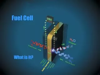
Introduction Overall Reaction Methane + Air --> Electricity + Hydrogen + Heat + CO2
Introduction Gas Reformer Water SynGas Electricity Air Fuel Cell Heat POR Hydrogen Pressure Swing Adsorption Exhaust
Fuel Cell-Chemistry SynGas POR H2 + CO H2 H2O CO2 CO O- O- “Air” Air O2 N2 Solid Oxide Electrolyte is porous to O-
Fuel Cell-Electricity Electrons SynGas POR H2 H2O CO2 CO Load O- O- “Air” Air O2 N2
Fuel Cell-Challenges SynGas POR H2 Hot SynGas + CO H2 H2O CO2 CO Recover H2 O- O- “Air” Air O2 N2 Hot Air Recover Heat
Process Description Fuel Preparation Fuel Cell Air Preparation Post Processing
Fuel Preparation - 100 Fuel Preparation Fuel Cell Air Preparation Post Processing
Air Preparation - 200 Fuel Preparation Fuel Cell Air Preparation Post Processing
Fuel Cell - 300 Fuel Preparation Fuel Cell Air Preparation Post Processing
Post Processing - 400 Fuel Preparation Fuel Cell Air Preparation Post Processing
Sulfur Purge 25°C 0.0002 kmol/hr H2S = 100% Desulfurizer Pure Natural Gas 25°C 0.33 kmol/hr CH4 = 100% Natural Gas Inlet 25°C 0.33 kmol/hr CH4 = 99.9% H2S = 0.001%
Heat Exchangers • A=q/UFΔTlm • F = 0.9 • U = 30 W/m2°C • ΔTlm = (ΔT2 – ΔT1) / [ ln(ΔT2 / ΔT1) ]
Fuel Humidifier POC Vent 26°C Pure NG 25°C 0.3 kmol/hr CH4 = 100% Humidified NG 273°C 0.67 kmol/hr H2O = 56% CH4 = 44% Area = 2.6 m2 q = 1.8 kW Recycled Water 5°C 0.37 kmol/hr H2O = 100% Cooled POC 283°C 3.51 kmol/hr N2 = 86% O2 = 9% H2O = 4% CO2 =1%
Fuel Preheater POR 850°C 1.3 kmol/hr H2O = 47% H2 = 29% CO2 = 23% CO = 1% Humidified NG 273°C Area = 6.3 m2 q = 5.3 kW Heated HNG 840°C Cooled POR 479°C
COMB-105 R-104 Reformer R-104 CH4 + H2O → CO + 3H2 CH4 + 2H2O → CO2 + 4H2 Depleted Air POC Pure NG SynGas Heated HNG q = 17 kW SynGas 734°C 1.26 kmol/hr H2 = 73% CO = 21% H2O = 3% CO2 = 2% Heated HNG 840°C 0.67 kmol/hr H2O = 56% CH4 = 44%
COMB-105 R-104 Combustor COMB-105 CH4 + 2O2 → CO2 + 2H2O Depleted Air POC Pure NG SynGas Heated HNG q = -17 kW Pure NG 25°C 0.03 kmol/hr CH4 = 100% Depleted Air 850°C 3.48 kmol/hr N2 = 87% O2 = 11% H2O = 2% POC 784°C 3.51 kmol/hr N2 = 86% O2 = 9% H2O = 4% CO2 =1%
Water Gas Shift Reactor CO + H2O → CO2 + H2 WGS Exhaust 480°C 1.26 kmol/hr H2O = 46.5% H2 = 30% CO2 = 23.2% CO = 0.3% Cooled POR 480°C 1.3 kmol/hr H2O = 47% H2 = 29% CO2 = 23% CO = 1%
Fuel Cell Depleted Air 850°C 3.48 kmol/hr O2 = 11.5% CO + ½ O2 → CO2 H2 + ½ O2 → H2O SynGas 750°C 1.26 kmol/hr H2 = 73% CO = 21% H2O = 3% CO2 = 2% POR 850°C 1.3 kmol/hr H2O = 47% H2 = 29% CO2 = 23% CO = 1% Heated Air 650°C 3.88 kmol/hr O2 = 21%
Pressure Swing Adsorber H Exhaust 25°C 0.38 kmol/hr H2 = 100% Air Inlet 25°C 0.13 kmol/hr Uncondensed Gases 5°C 0.68 kmol/hr H2 = 56% CO2 = 43% Purge 25°C 0.43 kmol/hr CO2 = 68%
Economic Components • Capital Costs • Operating Costs • Income Generated • Payback Period • Return on Investment
Capital Cost Assumptions • Cap Cost Program • Analysis, Synthesis, and Design of Chemical Processes • Compares to Peters and Timmerhaus • Stainless Steel
Lang Factor • Fluid Processing = 4.74 • Includes: • Construction material and overhead • Labor • Contract engineering • Contingency • Site development • $40,000 X 4.74 = $190,000
Operating Costs • Fuel: 0.33 kmol/hr = 260,000 BTU/hr = 0.26 therms/hr • Tennessee Valley industrial rate = $7.70/therm • Labor included at site
Income • Electricity = 25kW • Price = $0.10/kWhr • Hydrogen = 0.38 kmol/hr = .76 kg/hr • Tennessee Valley industrial rate = $11.64/kg
Investment Results Non-discounted Payback = 2.4 Years Return on Investment = 41%
Conclusions • Rate of return and payback period are interesting • Emerging technology means cost may decrease
Questions for the Board • What areas require more detail? • What locations should be investigated? • Should we enlist an electro-chemistry team? • Should we enlist an electrical engineering team?