Download
1 / 14
140 likes | 258 Views
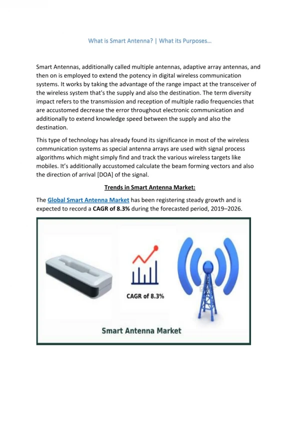
This paper presents advancements in smart antenna technology for Time Division Multiple Access (TDMA) systems. It explores the implementation of adaptive antennas to improve uplink and downlink performance, highlighting enhanced spectrum efficiency and interference suppression techniques. The deployment of smart antennas with multiple receive antennas aids in enhancing capacity while minimizing co-channel interference. The paper also discusses MIMO techniques and real-time performance improvements achieved using dual-polarized antennas and advanced signal processing, paving the way for future innovations in wireless communications.

E N D
SMART ANTENNAS FOR TDMA Jack H. Winters AT&T Labs - Research Red Bank, NJ 07701-7033 jhw@research.att.com September 7, 2000
Uplink Adaptive Antenna SIGNAL SIGNAL OUTPUT INTERFERENCE BEAMFORMER WEIGHTS BEAM SELECT SIGNAL BEAMFORMER INTERFERENCE Smart Antennas for TDMA • Key enhancement technique to improve system capacity and user experience • Leverage Smart Antennas currently in development/deployment for IS-136 TDMA Downlink Switched Beam Antenna SIGNAL OUTPUT Aggressive frequency re-use(7/21,4/12,1/3) High spectrum efficiency Increased co-channel interference Smart antennas provide substantial interference suppression for enhanced performance
Smart Antennas 11.3 ft Prototype Dual Antenna Handset Rooftop Base Station Antennas Prototype Smart Antenna for Laptops
SMART ANTENNAS IN SECOND GENERATION SYSTEMS • IS-136 TDMA: • On uplink, with two receive antennas, in 1999 changed from maximal ratio combining to optimum combining • Software change only - provided 3-4 dB gain in interference-limited environments • Combined with power control on downlink (software change only) - increased capacity through frequency reuse reduction • Use of 4 antennas (adaptive array uplink/multibeam, with power control, downlink) extends range and/or doubles capacity (N=7 to 4 or 3) • Clears spectrum for EDGE deployment (2002) • Limited deployment at base stations
RADIO UNIT ADAPTIVE ANTENNA RECEIVER 4 Branches RSSI, BER Shared LPAs Power Control DUPLEXERS Atten SPLITTER TRANSMITTER Atten Atten Atten BEAM SCANNING RECEIVER 1 per N radios • IS-136 Smart Antenna System • 4 Branch adaptive antenna uplink for range extension and interference suppression • Fixed switched beam downlink with power control for increased coverage and capacity • Uplink and downlink are independent • Shared linear power amplifiers reduce amplifier requirements to handle maximum traffic load
Smart Antenna System • Dual-polarized slant 45° PCS antennas separated by10 feet and fixed multibeam antenna with 4 - 30° beams • 4 coherent 1900 MHz receivers with real-time baseband processing using 4 TI TMS320C40 DSPs
INTERFERENCE SUPPRESSION - OFFSET INTERFERER 0 -0.5 -1 -1.5 -2 -2.5 -3 -3.5 -4 10 20 30 0 Spatial Diversity: S/I = 0dB, AAA with 4 antennas vs. REF with 2 antennas • AAA(avg.) • REF (avg.) • AAA (data) • REF (data) BER SNR (dB)
ADAPTIVE ARRAYS IN EDGE Spatial-Temporal processing using DDFSE for interference suppression
EDGE with Interference Suppression in a Typical Urban Environment Rx DDFSE Equalizer Channel Decoder Output Data Rx Block Error Rate Signal -to-Interference Ratio (dB) Wireless Systems Research Dual Diversity Receiver Using Delayed Decision Feedback Sequence Estimator for Joint Intersymbol Interference and Co-channel Interference Suppression EDGE Smart Antenna Processing • Simulation results show a 15 to 30 dB improvement in S/I with 2 receive antennas • Real-time EDGE Test Bed supports laboratory and field link level tests to demonstrate improved performance
MIMO-EDGE • Goal: 4 transmit / 4 receive antennas in EDGE can theoretically increase capacity 4-fold with the same total transmit power (3.77X384 kbps = 1.45 Mbps is actual theoretical increase) • Issues: • Joint spatial-temporal equalization • Weight adaptation • Mobile channel characteristics to support MIMO-EDGE • Our approach: • Development of multi-antenna EDGE testbed • Development of 2X2 and 4X4 DDFSE architecture with MMSE combining using successive interference cancellation • Mobile channel measurements
EDGE with Wideband OFDM - MIMO Downlink • High data rates (>1 Mbps) required on downlink only • OFDM eliminates need for temporal processing => simplified MIMO processing for much higher data rates • With 1.25 MHz bandwidth, QPSK, OFDM-MIMO with 4 antennas at base station and terminal => 10 Mbps downlink
SMART ANTENNA EVOLUTION • IS-136: • Optimum combining uplink / power control downlink at all base stations with existing 2Rx/1Tx antennas • 4Rx/4Tx antenna upgrade (adaptive uplink/multibeam downlink) for N=7 to 4 to clear spectrum for EDGE • EDGE: • S-T processing with IS-136 smart antennas (Data followed by VoIP) • MIMO-EDGE (1.5 –2.4 Mbps) • Wideband OFDM-MIMO downlink (10-40 Mbps)