System Level Design Space Exploration for MPSoC: Methods, Algorithms and New Infrastructure
500 likes | 681 Views
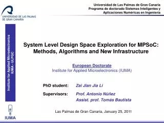
Universidad de Las Palmas de Gran Canaria Programa de doctorado Sistemas Inteligentes y Aplicaciones Numéricas en Ingeniería. System Level Design Space Exploration for MPSoC: Methods, Algorithms and New Infrastructure. European Doctorate Institute for Applied Microelectronics (IUMA).

System Level Design Space Exploration for MPSoC: Methods, Algorithms and New Infrastructure
E N D
Presentation Transcript
Universidad de Las Palmas de Gran Canaria Programa de doctorado Sistemas Inteligentes y Aplicaciones Numéricas en Ingeniería System Level Design Space Exploration for MPSoC: Methods, Algorithms and New Infrastructure European Doctorate Institute for Applied Microelectronics (IUMA) PhD student: Zai Jian Jia Li Supervisors: Prof. Antonio Núñez Assist. prof. Tomás Bautista Las Palmas de Gran Canaria, January 25, 2011
OUTLINE • Introduction and context • Motivation, challenges and goals • Approaches and contributions • Results • Conclusions and future work
INTRODUCTION • Systems-on-Chip design challenges • The continuous technology progress is leading to a major capacity of integration on chip. • System composted of a big number and variety of components: processing elements (PEs), network elements (NEs), storages elements (SEs); I/O devices… • As a result, this Increasing level of integration is leading to more complex embedded Systems-on-Chip (SoC). • This issue also represents several challenges for the system designers.
INTRODUCTION • Challenges (I) • Heterogeneous architectural components: SoC composed of multiple and different types of PEs, SEs, NEs… Example: Multiprocessor System-on-Chip (MPSoC). => Flexible and reusable platform for a family of product and easily modified for the market needs. • Exploration of a large number of design decisions: designers have to make decisions about a large amount of design decisions or design options. Example: number and types, mapping, architectural topology, HW/SW partition, allocation of the components in the architecture… => The more flexible and complex the platform is, the larger number of design options should be taken into account.
INTRODUCTION • Challenges (II) • Multiple design constraints: in addition to the huge number of design decisions that should be explored, designers also have to take into account many design objectives. Example: performance, cost/area, power consumptions… => Optimal solution inside the design space that satisfy the design constraints: efficiency and without over-dimensioning. • New techniques and generic framework: to assist to designers in the exploration and design process. We would need flexible and reusable approaches, without resorting to ad-hoc strategies designed for particular cases. => Strategies to carry out the design process in a time efficient way, as well as to reduce significantly the effort of designers.
INTRODUCTION • System level design (SLD) • SLD has been proposed as a complement to the traditional design methods at Register Transfer Level (RTL), as well as to improve the productivity of system designers. • Essential difference between SLD and RTL: SLD works at a higher abstraction level => elements with a higher granularity level and less implementation details. • Working at a higher abstraction level implies to trade off certain accuracy with respect to RTL design. • System level design indeed presents important benefits to the system designers.
INTRODUCTION • Some benefits of System level design • Simplify significantly the design effort: new design or modification of a previous design can be obtained in an easier way than if using a lower abstraction level. • Speed up the simulation time: as consequence of working with less implementation details, system level simulations can run 2 and 3 orders of magnitude faster than RTL simulations => rapid exploration of large number of design points or design solutions. • Making decisions at an earlier stage of design process: allow designers to have a clear overview and the impacts of different design decisions on system behaviours => without building or developing a full-detailed system design.
OUTLINE • Introduction and context • Motivation, challenges and goals • Approaches and contributions • Results • Conclusions and future work
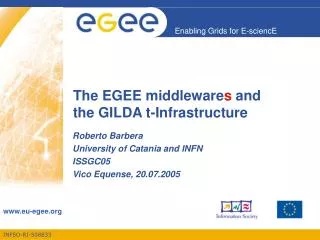
Design space dimension 3 Design point C Design space Dd3 B Design point B Design point B Dd3 A Design point A Design point A Design space dimension 2 Dd2 B Dd2 A Dd1 B Dd1 A Design point D Design point E Design space dimension 1 MOTIVATION AND GOALS Context of this work: Design Space Exploration at System Level.
Design objective 1 Design space dimension 3 Design point C Design point C Design space Dd3 B Design point B Design point B Design point B Solution(s) or candidate solution(s) Design objective 3 Dd3 A Design point A Design point A Design point A Design space dimension 2 Dd2 B Dd2 A Dd1 B Dd1 A Design point D Design point D Design objective 2 Design point E Design point E Design space dimension 1 MOTIVATION AND GOALS Context of this work: Design Space Exploration at System Level.
MOTIVATION AND GOALS • Design Space Exploration (DSE) for MPSoC at System level • System-level DSE for MPSoC often can be seen as a multiobjective optimization design problem. • The more design options, the larger the resulting design space is => and the more effort and time is needed to carry out the DSE. • Components of the DSE process Search methods, evaluation techniques and generator of system design description.
The search method is used to travel systematically through the design space. • Goal: identify and select design points (from the design space) that are analyzed further by the evaluation techniques. • Different strategies: exhaustive search, random sampling, incorporating knowledge of design space (e.g., genetic algorithms), heuristic-based algorithms… Search method Design space MOTIVATION AND GOALS Components of system-level DSE process
Evaluation technique assess the quality of each design point selected by the search method. • The quality of solutions is measured in terms of different system metrics: packets/data processed per second, system traffic, number of each type of components actually used in the architecture… • System-level simulation and analytical methods (formal rules, mathematical formulations…) • The search method is used to travel systematically through the design space. • Goal: identify and select design points (from the design space) that are analyzed further by the evaluation techniques. • Different strategies: exhaustive search, random sampling, incorporating knowledge of design space (e.g., genetic algorithms), heuristic-based algorithms… Evaluation technique Search method System metrics Performace, power, cost… Design space MOTIVATION AND GOALS Components of system-level DSE process
Evaluation technique assess the quality of each design point selected by the search method. • The quality of solutions is measured in terms of different system metrics: packets/data processed per second, system traffic, number of each type of components actually used in the architecture… • System-level simulation and analytical methods (formal rules, mathematical formulations…) Generator of system description Application model Mapping model Design points descriptions System model Evaluation technique Search method Architecture model System metrics Performace, power, cost… Design space MOTIVATION AND GOALS Components of system-level DSE process
In the practice, many efforts are based on ad-hoc approaches: create manually, or use customized control scripts… • Rewrite these control scripts for different DSE => labour intensive, error-prone, bottlenecks of productivity… Generator of system description Application model Mapping model Design points descriptions System model Search method Architecture model System metrics Design space MOTIVATION AND GOALS Components of system-level DSE process Evaluation technique Performace, power, cost…
In the practice, many efforts are based on ad-hoc approaches: create manually, or use customized control scripts… • Rewrite these control scripts for different DSE => labour intensive, error-prone, bottlenecks of productivity… DSE infrastructure User specifications Generator of system description Application model Mapping model Design points descriptions System model Search method Architecture model System metrics Design space MOTIVATION AND GOALS Components of system-level DSE process AUTOMATIC Evaluation technique Performace, power, cost…
MOTIVATION AND GOALS • Goals • An approach to handle the increasing level of design options. • Strategies and algorithms to solve the multiobjective optimization design problem in a time and effort efficient way. • A framework that allows for incorporating different combinations of search strategies and evaluation techniques in an automatic and fast way. • A single and generic infrastructure for system-level DSE experiments, which provides a flexible and reusable environment to systematically explore the design space without resorting to ad-hoc efforts.
OUTLINE • Introduction and context • Motivation, challenges and goals • Approaches and contributions • Results • Conclusions and future work
Design options or design decisions Topology of the platform Number and type of components Tasks migration HW/SW partition Resources allocation and organization Tasks clustering Storage capacity Different clock domains … Scheduling policy … APPROACHES AND CONTRIBUTIONS • “Dimension-oriented DSE approach” • A novel concept and methodology for system-level MPSoC DSE. • A large design space defined by a huge number of design options can be explicitly separated and hierarchically organized into dimensions or exploration levels. Platform dimension Topology of the platform Number and type of components Tasks migration Arch. component dimension HW/SW partition Resources allocation and organization Tasks clustering Storage capacity Mapping dimension Different clock domains Scheduling policy
APPROACHES AND CONTRIBUTIONS • Dimension-oriented DSE approach: benefits • Extensibility: remove and add new exploration levels with additional design options. • Flexibility: explore simultaneously all dimensions of the design space or to fix one or more of these dimensions (e.g., a fixed architecture) and focus the exploration within other dimensions. Use a single search methods for exploring the whole design space, or use a separate and different search method to co-explore the design space => not perform the DSE as multiple independent explorations, but the results from all dimensions are simultaneously taken into account.
¿ ? is better than Result after a single evaluation: A is better than B = or ¿ ? is better than APPROACHES AND CONTRIBUTIONS • Dimension-oriented DSE approach If no information is exchanged between different search methods in the co-exploration process, we can have an under-exploration problem and/or even worse, we cannot ensure the convergence. Solution:Establish explicit relationships between different search methods used in the co-exploration process. There are many ways, e.g., by means of hierarchical fitness functions => the search methods that work at higher abstraction dimensions require more information for a better overview of the design space.
APPROACHES AND CONTRIBUTIONS • “NASA framework” • NASA (Non Ad-hoc Search Algorithm) is a modular infrastructure for system-level MPSoC DSE experiments. • A software environment that allows designers to deploy our dimension-oriented approach, as well as to integrate a generator of system design description. • A single and generic framework that allows for integrating different combinations of search methods and evaluation techniques in a plug & play fashion. • A flexible and reusable infrastructure to carry out system-level multidimensional DSE experiments in a fast and automatic way.
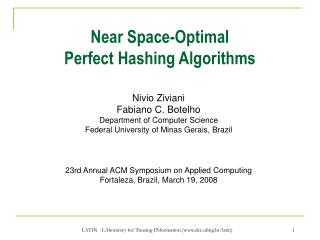
User specifications Metrics reader Components Platform Connectivity Arch. Platform Generator Feasibility Checker Search Application specifications Platform instance Modules configuration Architectural components Architecture instance Architecture constraints Design-options files (checked) Components specifications Tasks and channels Mapping Architectural intermediate file Design-options files (checked) Design-options files Fitness files Translator Fitness function Platform Evaluator Architectural Components Simulator Mapping Application model System model Mapping model Architecture model APPROACHES AND CONTRIBUTIONS • NASA framework
User specifications #defineNUMBER_SEARCH 3 #define TYPE_SEARCH_1 “GA” #define SOURCE_SEARCH_1 “../search/GA/” … #define MAX_NUMBER_PE 3 #define MAX_NUMBER_SE 2 #define MAX_NUMBER_NE 3 … #define TYPE_PE_1 “ARM” #define PARAMETER_FILE_PE1 “../library/PE/arm.txt” … #define TYPE_SE_1 “SDR” #define PARAMETER_FILE_SE1 “../library/SE/sdr.txt” … #define NUMBER_TASKS 7 #define NUMBER_CHANNLES 12 #define TASK1 “RGB2YCrCb” #define TASK1_SOURCE “../app/rgb2ycrcb/” … //Type PE PE1=ARM PE2=MIPS PE3=PPC //Type SE SE1=SDR SE2=DDR //Type NE NE1=BUS NE2=XBA NE3=P2P Num. NE=3 Num. SE=2 Num. PE=3 … … Application specifications Modules configuration Architecture constraints Components specifications APPROACHES AND CONTRIBUTIONS
Element container BTU 3 BTU 4 BTU 5 BTU 1 BTU 2 BTU 6 User specifications 2 3 7 1 1 1 1 1 1 2 2 2 2 2 2 3 3 3 3 3 3 4 4 4 4 4 4 5 5 5 5 5 5 Meta-platform 1 //Type PE PE1=ARM PE2=MIPS PE3=PPC //Type SE SE1=SDR SE2=DDR //Type NE NE1=BUS NE2=XBA NE3=P2P Num. NE=3 Num. SE=2 Num. PE=3 … … 4 Network 1 6 Application specifications 5 Modules configuration Network 2 Network 3 Architecture constraints Network 4 Network 5 Network 6 Components specifications 1 2 3 4 5 Network container BTU Basic Topology Unit is a logical pattern composed of a number of the element containers and a network container APPROACHES AND CONTRIBUTIONS
Element container BTU 4 BTU 1 BTU 6 BTU 5 BTU 2 BTU 3 User specifications 2 3 7 1 1 1 1 1 1 2 2 2 2 2 2 3 3 3 3 3 3 4 4 4 4 4 4 5 5 5 5 5 5 Meta-platform 1 //Type PE PE1=ARM PE2=MIPS PE3=PPC //Type SE SE1=SDR SE2=DDR //Type NE NE1=BUS NE2=XBA NE3=P2P Num. NE=3 Num. SE=2 Num. PE=3 … … 4 Metrics reader Components Platform Connectivity Arch. Platform Generator Feasibility Checker Network 1 Search 6 Application specifications 5 Platform instance Modules configuration Network 2 Network 3 Architectural components Architecture instance Architecture constraints Design-options files (checked) Network 4 Network 5 Network 6 Components specifications Tasks and channels Mapping Architectural intermediate file Design-options files (checked) Design-options files 1 2 3 4 5 Fitness files Translator Network container Fitness function BTU Platform Evaluator Architectural Components Basic Topology Unit is a logical pattern composed of a number of the element containers and a network container Simulator Mapping Application model System model Mapping model Architecture model APPROACHES AND CONTRIBUTIONS
Search SA Dimension-oriented DSE approach: 1) Multiple Search Algorithms 2) Different (tailored) search algorithm per dimension 3) Fixe one dimension Platform Search Platform SA Architectural components Architectural components Mapping SA Mapping 1 Search Algorithm (SA) Adaptor in Adaptor out SA APPROACHES AND CONTRIBUTIONS
… … … … … … … … … … … … Design-options file dpla1 Platform string sub-string Platform dplak Search Networks Architectural elements darc1 Architectural components string Architectural components darck Processors Memories Mapping dmap1 Mapping string dmapk Tasks Channels dpla1 dplaj dplak … … darc1 darcj darck … … dmap1 dmapj dmapk … … Design point (dpk) APPROACHES AND CONTRIBUTIONS
User specifications Metrics reader Components Connectivity Platform Arch. Platform Generator Feasibility Checker Search Application specifications Platform instance Modules configuration Architectural components Architecture instance Architecture constraints Design-options files (checked) Components specifications Tasks and channels Mapping Architectural intermediate file Design-options files (checked) Design-options files Fitness files Translator Fitness function Platform Evaluator Architectural Components Simulator Mapping Application model System model Mapping model Architecture model APPROACHES AND CONTRIBUTIONS
BTU 1 BTU 1 BTU 2 BTU 4 Users specification NE1 = Bus NE2 = XBA 1 1 1 1 2 2 2 2 3 3 3 3 4 4 4 4 5 5 5 5 Components Connectivity Feasibility Checker Infeasible platform string Feasible platform string NE1 NE2 NE3 NE4 NE5 NE6 1 2 0 0 0 0 … … NE1 NE2 NE3 NE4 NE5 NE6 1 0 0 2 0 0 … … Checked design-options file Tasks and channels Infeasible platform (isolate BTU) Feasible platform bus bus BTU 3 BTU 2 BTU 3 xba BTU 4 BTU 5 BTU 6 BTU 5 BTU 6 xba APPROACHES AND CONTRIBUTIONS
BTU 2 BTU 1 BTU 1 BTU 4 Users specification NE1 = Bus NE2 = XBA User specifications 1 1 1 1 2 2 2 2 3 3 3 3 4 4 4 4 5 5 5 5 Metrics reader Components Connectivity Platform Arch. Platform Generator Feasibility Checker Search Application specifications Infeasible platform string Feasible platform string Platform instance NE1 NE2 NE3 NE4 NE5 NE6 1 2 0 0 0 0 … … NE1 NE2 NE3 NE4 NE5 NE6 1 0 0 2 0 0 … … Modules configuration Checked design-options file Architectural components Architecture instance Architecture constraints Design-options files (checked) Components specifications Tasks and channels Mapping Architectural intermediate file Design-options files (checked) Design-options files Infeasible platform (isolate BTU) Feasible platform Fitness files bus bus Translator Fitness function BTU 3 BTU 2 BTU 3 Platform Evaluator Architectural Components xba Simulator Mapping BTU 4 BTU 5 BTU 6 BTU 5 BTU 6 Application model System model Mapping model Architecture model xba APPROACHES AND CONTRIBUTIONS
Architectural intermediate file Sesame Translator CASSE Translator Translator module YML-basad architecture model Command lines based architecture model APPROACHES AND CONTRIBUTIONS • Translator module converts NASA’s internal format of a design point to the specific format required by each evaluation technique. • For example, integration of a new simulator in NASA only requires the adaptation of the Translator module. Different system-level simulators
User specifications Metrics reader Components Connectivity Platform Arch. Platform Generator Feasibility Checker Search Application specifications Platform instance Modules configuration Architectural components Architecture instance Architecture constraints Design-options files (checked) Components specifications Tasks and channels Mapping Architectural intermediate file Design-options files (checked) Design-options files Fitness files Translator Fitness function Platform Evaluator Architectural Components Simulator Mapping Application model System model Mapping model Architecture model APPROACHES AND CONTRIBUTIONS
APPROACHES AND CONTRIBUTIONS • “Heuristic-based mapping algorithms” • DSE experiments: using a single genetic algorithm vs multiple genetic algorithms. • Hierarchical DSE strategy with heuristic-based mapping algorithms => Fixed platform, variable architectural components and mappings. • Objective:multi-objective optimization mapping problem => optimal configuration of a target platform for the mapping of a real-time application, while achieving real-time constraint, minimizing system traffic load, maximizing resource usage as well as the load balancing.
APPROACHES AND CONTRIBUTIONS • Heuristic-based mapping algorithms • Estimation phase: • Heuristic algorithms and analytical estimation function => exploring and pruning the design space. • Map a minimum number of logical clusters onto the components of the MPSoC platform => constraints: real-time, system traffic load, load balancing and resource usage. • Simulation phase: • Candidate solutions obtained in estimation phase are assessed with a system-level simulator. • Analytical estimation usually focuses on the relevance of subset of design decisions, as well as often fail to consider non-linear system behaviours => make an accurate evaluation difficult without the use of simulation.
HW/SW partitioning Application specification Tasks clustering Static performance estimation Assignment Real-time constraint NASA configuration Architectural template Potential mappings Search Arc. Platform Gen. Simulator Components library Feasibility checker Evaluator Translator Estimation phase Simulation phase Select mapping Application task graph system model generator System-level simulator No satisfied Constraints Satisfied Best mapping APPROACHES AND CONTRIBUTIONS • Heuristic-based mapping algorithms
OUTLINE • Introduction and context • Motivation, challenges and goals • Approaches and contributions • Results • Conclusions and future work
RESULTS • Co-exploration vs traditional exploration DSE with multiple genetic algorithms (3GA) vs a single genetic algorithm (1GA). Target application:Visual tracking algorithm (ULPGC) System level simulator:CASSE (ULPGC)
10 iterations 20 iterations 30 iterations 40 iterations 3GA 3GA 1GA 1GA RESULTS • Co-exploration vs traditional exploration
Metrics to compare the quality of different DSE approaches: • Convergence • Diversity • Coverage RESULTS • Co-exploration vs traditional exploration CONVERGENCE COVERAGE DIVERSITY
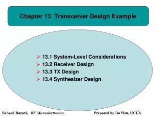
3GA Real-time constraint 1GA Local optima solutions 3GA can achieve to solutions satisfying the real-time constraint after 15~19 iterations. RESULTS • Co-exploration vs traditional exploration • In this set of experiments: fitness values=> performance (packets/s). • 3GA can converge progressively to solutions with a higher fitness value, while 1GA often cannot converge to solutions with higher fitness value (e.g., cannot achieve to the real-time constraint).
RESULTS • Co-exploration vs traditional exploration 1GA: after 40 iterations
3GA: after 40 iterations RESULTS • Co-exploration vs traditional exploration
3GA: after 10 iterations 3GA: after 20 iterations 3GA: after 30 iterations 3GA: after 40 iterations These solutions still need to be refined for their validations RESULTS • Co-exploration vs traditional exploration
RESULTS • Hierarchical strategy vs Co-exploration • DSE using our heuristic algorithms to explore and prune the design space vs Co-exploration using 2GA. • Target MPSoC platform, and variable architectural components and mappings. • Quality of DSE in term of the average runtime of DSE experiments: • Co-exploration: 60 simulations x 30 second per simulation = 1800 s. • Hierarchical:30 ~ 90 s => 2 orders of magnitude more efficient. • Quality of design solutions in term of four design objectives: (1) Number of resources actually used; (2) resources usage; (3) Minimize PE load unbalancing; (4) Minimize system traffic load.
RESULTS • Hierarchical strategy vs Co-exploration (1)Number of resources actually used;(2)resources usage; (3)Minimize PE load unbalancing;(4)Minimize system traffic load. Higher quality solutions After 20 iterations • Co-exploration approach also can achieve these optimal solutions or even better solutions => running more iterations. • Co-exploration with 2GA can provide a set of Pareto Optima solutions=> designers decide which strategy to used according to their need.
OUTLINE • Introduction and context • Motivation, challenges and goals • Approaches and contributions • Results • Conclusions and future work
CONCLUSIONS AND FUTURE WORK • The main goal pursues new approaches that facilitate the system-level design space exploration process => concepts, infrastructure, methods and algorithms. • It is important to stress that system-level design has been proposed as a complement of the traditional design methods => candidates solutions have to be refined for their validation. • As future work, it would be interesting to link our approaches to a design flow at lower abstraction level. • Develop more DSE experiments, integrating other search techniques, simulation tools and application domains, etc, in order to prove progressively the full capability of our approaches.
Universidad de Las Palmas de Gran Canaria THANKS YOU VERY MUCH FOR YOUR ATTENTION! Las Palmas de Gran Canaria, January 25, 2011
Universidad de Las Palmas de Gran Canaria Programa de doctorado Sistemas Inteligentes y Aplicaciones Numéricas en Ingeniería System Level Design Space Exploration for MPSoC: Methods, Algorithms and New Infrastructure European Doctorate Institute for Applied Microelectronics (IUMA) PhD student: Zai Jian Jia Li Supervisors: Prof. Antonio Núñez Assist. prof. Tomás Bautista Las Palmas de Gran Canaria, January 25, 2011