Ext Strips
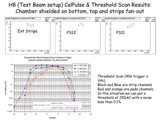
H8 (Test Beam setup) CalPulse & Threshold Scan Results: Chamber shielded on bottom, top and strips fan-out. Ext Strips. PS12. PS11. Threshold Scan (40k trigger x Vth). Black and Blue are strip channels Red and orange are pads channels.

Ext Strips
E N D
Presentation Transcript
H8 (Test Beam setup) CalPulse & Threshold Scan Results:Chamber shielded on bottom, top and strips fan-out Ext Strips PS12 PS11 Threshold Scan (40k trigger x Vth). Black and Blue are strip channels Red and orange are pads channels. In this situation we can put a threshold of 25DAC with a noise less than 0.1%
TTP(portable USB Test setup) CalPulse Results:Chamber shielded on bottom, top and strips fan-out s~3.2-4.4 Int Strips s~3.4-4.5 Ext Strips s~3.5-6 PS12 Pads s~3.3-4.8 PS11 Pads
TTP CalPulse Results:Chamber shielded on bottom, top and strips fan-out s~3.2-4.4 Int STrips s~3.4-4.5 Ext STrips s~3.3-4.8 PS11 s~3.5-6 PS12
Main H8(and confirmed byTTP) Measurements and Conclusion • No MSPL effects on the Noise. • Shields need on Bottom, Strips Fan-Out, Top. Good results with all the shields connected to the gnd plane. • Hybrids with AnDig/DigGnd connected less noisy.
Timing Studies: • We latched the signal from 1 to 4 clock cycles, to catch the slow rising GEM signal, tests revealed the possibility of using more clk cycles without degrading the level of the noise. • To increase the drift velocity we can replace the induction gap resistor in the H.V. divider. A good value could be 1.2/1.5M. • In order to have a bigger improvement of the rising time we could use Ar/CO2/CF4 that increase not only the drift velocity but also the number of primary clusters in the drift gap (more effective than changing only the induction field).(We have to be careful because using CF4, the gain of each GEM foil will be reduced.)