Download
1 / 44
440 likes | 580 Views
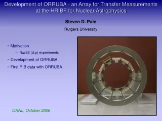
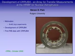
Development of ORRUBA - an Array for Transfer Measurements at the HRIBF for Nuclear Astrophysics. Steven D. Pain Rutgers University. Motivation N 82 (d,p) experiments Development of ORRUBA First RIB data with ORRUBA. ORNL, October 2006. ORRUBA motivation.

E N D
Development of ORRUBA - an Array for Transfer Measurements at the HRIBF for Nuclear Astrophysics Steven D. Pain Rutgers University • Motivation • N82 (d,p) experiments • Development of ORRUBA • First RIB data with ORRUBA ORNL, October 2006
ORRUBA motivation Neutron magic-number nuclei at waiting points HRIBF yields N=82
Requirements of ORRUBA Proton Angular Distribution 25 20 20 15 15 Energy (MeV) Yield 10 10 5 5 0 0 0 30 60 90 120 150 180 Laboratory Angle (deg) Proton Energy-Angle Systematics 132Sn(d,p) @ 4.5 MeV/A • High Solid Angular Coverage • Good energy and angular resolution • Large dynamic range
Requirements of ORRUBA Elastically scattered carbon Elastically scattered deuterons Protons from (d,p) Elastically scattered protons
Oak Ridge Rutgers University Barrel Array (ORRUBA) Design • 2 rings – q < 90°: 12 telescopes (1000mm R + 65mm NR) • – q > 90°: 12 detectors (500mm R) • 324 channels in total (288 front side, 36 back side)
ORRUBA Detector Design 8 strip non-resistive detectors 4 strip resistive detectors
Prototype ORRUBA Detectors Perform tests to determine: Have 1/3 detectors in house: • Correct operation of detector (measurement of position and energy independently) • Energy Resolution • Position Resolution • Depletion Depth for thick detectors • Thirteen 1000mm detectors • Several 65mm detectors • One 500mm detector • Number of prototypes
1000mm Detector Performance - Depletion Detector not fully depleted 5.8 MeV a-particles only penetrate 30mm into detector Either increase energy, or use more penetrating particles a particles into back face a particles into junction face Regions of poor charge collection 80 V Full bias 140 V 60 V 20 V 100 V Energy (a.u.) Energy (a.u.) Position (a.u.) Position (a.u.)
Proton Scattering Tests 11.5 MeV 12.0 MeV Energy (a.u.) Energy (a.u.) Position (a.u.) Position (a.u.)
Depletion Depths Effect limited to back 10% of detector Effect results in < 7% limit in maximum energy
Detector Test Results 1000mm Detector 1000mm Detector • Detectors perform well, with good energy and position resolution • Detectors deplete >90% of their volume 0.5mm FWHM on 11.5 MeV protons 68 keV FWHM on 11.5 MeV protons Thinner Detectors • 65mm non-resistive detectors for DE layer, with greater segmentation (8 strips) • Detectors at assembly stage Energy (a.u.) 500mm detectors just out of implant stage Position (a.u.)
124Sn(d,p)125Sn ORRUBA Test Setup 550 MeV 124Sn
124Sn(d,p)125Sn ORRUBA Test Setup 300mm 500mm 100mg CD2 target @ 60° 1000mm + 65mm 1000mm
124Sn(d,p)125Sn ORRUBA Test Data – 1000mm detector 10.0 CoM resolution ~150keV Counts 7.5 Energy (MeV) 5.0 0 1 2 3 4 5 2.5 Excitation Energy (MeV) 80 90 Lab Angle (deg) 100 110 120 130 140
132Sn(d,p) Simulations Total CoM Resolution ~ 220 keV E resolution ~ 65 keV Pos resolution ~ 110 keV Target ~ 155 keV CoM Resolution (qlab< 80°) ~ 175 keV E resolution ~ 55 keV Pos resolution ~ 80 keV Target ~ 135 keV
Summary • Measurement of (d,p) reactions on heavy fission fragments requires high-solid angular coverage around 90°, with high resolution in energy and angle • ORRUBA developed to meet these requirements, and be as flexible as possible • Over 1/3 of detectors in house – arriving currently • First (d,p) data taken with ORRUBA detectors. CoM resolution of 150 keV achieved with a 100mg/cm2 target @ 60 degrees • Early implementation of ORRUBA currently employed in the 130,132Sn(d,p) experiments
Collaborators J.A. Cizewski, R. Hatarik, K.L. Jones, S.D. Pain, M. Sikora, J.S. Thomas Rutgers University M.S. Johnson Oak Ridge Associated Universities D.W. Bardayan, J.C. Blackmon, C.D. Nesaraja, M.S. Smith, D. Shapira, F. Liang Oak Ridge National Laboratory R.L. Kozub Tennessee Tech. University J. James, R.J. Livesay Colorado School of Mines A. Chae, Z. Ma, B.H. Moazen University of Tennessee W.N. Catford, T. Swan University of Surrey
Angular Straggling Measurements Energy Position • 1000mm stopping at forward angles • 65mm non-resistive dE at forward angles 1.2mm FWHM on 5.85 MeV protons Angular straggling negligible at ~5 MeV
ORRUBA Vacuum Chamber Cut-away Target Manipulator Preamplifiers Beam Possible to mount SIDAR upstream, to cover more backward angles, via second preamplifier ring Detectors mounted from preamplifier ring, on linear bearings, to allow detector access, without un-cabling Preamplifier feedthroughs
1000mm Detector Performance – a particle tests Energy (a.u.) Position (a.u.) Guard ring effect (appears around 50V bias) independent of deposited energy 1.2 MeV
1000mm Detector Performance – a particle tests Energy (a.u.) Position (a.u.) Guard ring effect (appears around 50V bias) independent of deposited energy 1.2 MeV
ORRUBA Comparison • ORRUBA gives ~80% f coverage over the range 47° →132° • Pre-existing setup gives <30% coverage over the range 60° → 120° • Factor of ~4.5 times the solid angular coverage • Can perform experiments with more exotic (weaker) beams for given beam-time • Gain improved statistics from similar intensities • Can perform experiments with similar beam intensities with less beam-time
ORRUBA Vacuum Chamber and Preamplifiers Small cross for diagnostic detector Large cross target chamber Preamplifier ring Preamplifier ring Preamplifier Rails
ORRUBA + SIDAR Arrangement Target plane Beam 48° - 89° 91° - 132° 149° - 168°
130,132Sn(d,p) Experiments 20 15 10 ds/dW (mb/sr) 5 0 30 60 90 120 150 qlab (deg) Measure (d,p) either side of N=82, at Z=50 Measurements around N=82 more experimentally challenging Measurements of 130Sn(d,p) and 132Sn(d,p) due to be performed imminently Forward qc-o-m↔ back qlab Want to measure around 90o
Motivation for Developing ORRUBA • Experiments on fission fragments must be performed in inverse kinematics • Inverse kinematics results in forward peaks in the (CoM) angular distributions being dispersed over large range of back angles in the lab frame • The effects of the strongly inverse kinematics are dominant → suggests a general purpose array design • Measure excitation energies of states populated in the final nucleus with good resolution (~200keV due to target thickness effects) • Measure proton angular distributions (ℓ transfer + spectroscopic information)
130,132Sn(d,p) Setup ORRUBA telescopes ORRUBA telescopes
134Te(d,p) Motivation 135Xe 136Xe 134Xe 136I 133I 134I 135I 135Te 136Te 132Te 133Te 134Te N=82 Pre-solar diamond grains • Overabundance of light and heavy Xe isotopes • Heavy isotope anomaly: relative excesses of 134Xe and 136Xe do not correspond to average r-process abundances U. Ott, Planetary and Space Science 49 (2001) 763 • Suggested explanations: • Formation in intermediate neutron flux environment (between s & r process) • Rapid separation of Xe from its precursors (Te and I) in supernova ejecta • Low entropy r-process Effect of structure around N=82 shell closure
Effect of Shaping Time – 140mm detector Energy (a.u.) Energy (a.u.) Energy (a.u.) Position (a.u.) Position (a.u.) Position (a.u.) Counts Counts Counts Position (a.u.) Position (a.u.) Position (a.u.) 0.5ms 1.0ms 1.5ms
58Ni(d,p)59Ni Test @ 250 MeV CD2 (~150 mg/cm2 eff.) • First (d,p) data taken with ORRUBA detectors • Stable beam • 58Ni selected for convenience of acceleration p 58Ni 1000mm ORRUBA 65mm ORRUBA
58Ni(d,p)59Ni Test @ 250 MeV 400 CD2 (~150 mg/cm2 eff.) p 300 58Ni Energy Loss (a.u.) 200 1000mm ORRUBA 65mm ORRUBA 100 0 400 300 0 100 200 Residual Energy (a.u.)
58Ni(d,p)59Ni Test @ 250 MeV 12 12 8 8 Proton Energy (a.u.) Proton Energy (a.u.) 4 4 0 0 80 80 100 100 120 120 140 140 Angle (deg) Angle (deg) CD2 (~150 mg/cm2 eff.) p 58Ni 1000mm ORRUBA 65mm ORRUBA
ASICs • WashU (St Louis)/MSU ASICs system • Preamps, discriminators, logic and analog circuits all on one (16 channel) chip • 2 chips per chip board • 16 chip boards per motherboard • Multiplexed analog signals → single flash-ADC for entire system • Dramatic cost reduction per channel compared with conventional electronics • External preamps (need high gain) • Designed for non-resistive, low capacitance Si detectors
Fission Fragment Beam Production 3. Ionize atoms 2. Transport to ion source 4.Create Negative Ions 1. Create nucleus of interest