Download

1 / 34
340 likes | 558 Views
Mozaic trigger system for transverse momentum physics. G.Vesztergombi , A.Agocs, B.Bozsogi, A.Fulop CBM Collaboration Meeting GSI – Dubna 13-18 Oct , 200 8. Motivation for new measurements below = 20 GeV.

E N D
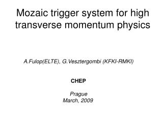
Mozaic trigger system for transverse momentum physics G.Vesztergombi, A.Agocs, B.Bozsogi, A.Fulop CBM Collaboration Meeting GSI – Dubna 13-18Oct,2008
Motivation for new measurements below = 20 GeV Practically no high or medium Pt data between Einc = 24 and 200 GeV Mysterious transition around 80-90 GeV: convex versus concave spectra Energy threshold for Jet-quenching? Emergence of Cronin-effect in pA interactions is completely unknown energy dependence centrality dependence particle type dependence particle correlations Production of Upsilon (9.5 GeV) particles near the threshold.
Beier (1978) NA49 (CERN) results at 158 FODS (IHEP) at 70 GeV
Y production Due to high mass ( 9.5 GeV/c2) two high pT particle in leptonic decay: pT > 3 GeV/c High selectivity for high pT pair even without PID
Benchmark NA49pp at E = 158 GeV 30 events/spill Events Energy > 3 GeV/c > 4 GeV/c > 5 GeV/c 2 106 158 100 1 0.01 Estimates with the assumption 1011 proton/sec 109 interaction/sec 1 day=1014 158 5 109 5 107 5 105 CBM Perspectives Suppression 10-1 10-2 10-3 1 day=1014 90 5 108 5 105 500 20 day=2 1015 90 1010 107 104 Suppression 10-3 10-6 10-10 20 day=2 1015 45 107 10 0 For symmetric nuclei max energy 90/2 assumed
Special requirements for Y-> e+e- and high pT Extremely high intensity - Pile-up Segmented multi-target - Relaxed vertex precision Straight tracks - High momentum tracks DREAM: 109 interactions/sec
p p p trans trans trans g E >= p >= 0 long Lab g E Beam Lab High transverse momentum means high 3-momentum Illustration for mid-rapidity at sqrt(s) 7 and 14 GeV ( ) ( ) ( ) E g gb 0 Lab p = long gb g 0 0 0 0 1 • 3.5 1.5 5.25 • 2.0 7.0 • 3.0 10.5 • 90 6.6 1.5 9.9 • 2.0 13.2 • 3.0 19.8
High ( > 5 GeV/c ) momentum Straight track x,y [cm] Px=Py= 3 GeV/c Pz = 10 GeV/c Px=Py = 1 GeV/c; Pz= 5 GeV/c z [cm]
“Straight” tracks from main vertex Tracks with pxz > pmin remains within the df(pmin) wedge 1-dim Hough – transform: f - histogram f , df N( fi) in df-bins Correct for bin boundary crossing: M(fi) = N(fi) + N(fi+1 ) in 2df-bins SELECTION on pxz
3 dimensional scheme k=3 i+1 k=2 i k=1 j j+1 Mosaic cells in plane “k” : M(i,j,k) (i,j) Corridor contains: M(i,j,k), M(i,j+1,k), M(i+1,j,k), M(i+1,j+1,k) k=1,2,3
MAPS vs Hybrid Vertex resolution: dz = 1 mm, dx,dy= 0.05 mm High intensity: radiation hard Practical 4+ 2 + 3 = 9 planes ( 4 Hybrids + 5 strips) Selectivity depends on the availability of TOF information
Silicon planes 4 hybrids 2 + 3 strips (XX,YY,ZZ) a delta * * * * * * * * * s = sqrt(XX*XX+YY*YY) - delta 2 4 Basic planes 6 Sagitta: 10-20 cm track sections are practically straight fractals
New algorithm Matching in #1 and #3 pixel planes in space Separate track matching in xand y for planes 5-9 Parallel processing: CORRIDOR # corNum Basic planes: #2 = (x2,y2,z2) pixel , #4 = (x4,y4,z4) pixel, #6 = (x6,z6) strip Straight tracking in #2 and #4 planes in space => (mx,bx) and (my,by) Approximation: starting direction is given by (mx,my) TUBE definition: x-tube: xi = mx*(zi-z2) +bx +parabol(x6,z6,zi) +/- deltaxi y-tube: yi = my*(zi-z2) +by +/- deltayi
4-5 GeV/c pT > 1.0
7-8 GeV/c pT > 1.0
9-10 GeV/c pT > 1.0
15-17 GeV/c pT > 2.5
20-40 GeV/c pT > 2.5
Acceptance - + pT Npoint=9 pxz
Pileup Fixed pT-cut at 1.8GeV/c No pileup : Tracks with ptin > 1.8: 1136 ptin < 1.8 but ptrec > 1.8: 430 Npileup = 10 : Tracks with ptin > 1.8: 1136 FAKE and ptrec error : 1 + 430 Npileup = 100 : Tracks with ptin > 1.8: 1136 FAKE and ptrec error : 28 + 430 Npileup = 1000 : Tracks with ptin > 1.8: 1136 FAKE and ptrec error : 464 + 430 No LOSS of GOOD tracks due to pileup (exhaustive search!!!) Number of FAKE triggers even in 1000-fold pileup is < 50 %
Pileup cont. • pT dependence: No pileup 1000-fold pileup • 1.8 GeV/c 430/1136 464+430/1136 • 2.0 GeV/c 312/704 363+312/704 • 2.2 GeV/c 208/453 306+208/453 • 2.4 GeV/c 151/301 265+151/301 • 2.6 GeV/c 103/213 205+103/213 • 3.0 GeV/c 52/154 168+ 52/154 The FAKE/GOOD ratio is moderately increasing with pT
Deviations within the tube dx Charge*dx
Difference between exact direction and mx pxz pT > 2.5 GeV/c pT > 1.0 GeV/c
Mozaic DAQ system Two separate systems: PRETRACKING network: Pixel [#2 , #4] + Strip [#6x] TRACK-QUALITY TUBE network: Pixel [ #1, #3] + Strip[#5x, #5y, #6y, #7x, #7y, #8x, #8y, #9x, #9y] In each network parallel CORRIDOR processors: CorID =corNUM Number of CORRIDOR processors: ndx*ndy Data select their routes according to plane number and corNUM In plane „zi” track-hit „xi,yi” calculates its corridor address: corNum = idx*ndy + idy
Corridor processors OLD system: consecutive cycling on all „planes” If only 2 points per plane: number of cycles = 2(4+2*5) = 214 = 16384 NEW system: cycling only on 3 „planes” (for pixels x and y has common cycle) If only 2 points per plane: number of cycles = 2(2+1) = 23 = 8 The PRETRACKING is producing a list containing: corNUM, x1,x3,x5,x7,x8,x9, y1,y3,y5,y6,y7,y8,y9 There is NO PROCESSING TIME in the TRACK-QUALITY TUBE network because It is only an ASSOCIATIVE memory which provides YES/NO. The gain in processing time (if only 2 points per plane): 211 = 2048-fold
Silicon tracker in FAIR-CBM experiment Special trigger for high intensity 1O9 interaction/sec in pp,pA reactions SIMULATION: 4 hybrid(pixel) + 5 strip = 9 silicon planes “Mosaic” front-end structure (dx,dy) regions in M(i,j,k) buffers. Exhaustive search for all tracks in (pmin,pmax) corridors. TEST RESULT: 1000-fold PILEUP in pC interactions Corridor-width optimized for tracks pT > 3 GeV/c Algorithm efficiency: 100 %, with some multiple solutions picking up some random points, giving practically the same track-parameters Highly parallel algorithm is well adapted for processor clusters. Can be adapted for AA to reconstruct ALL particles with low pT corridors
Physical mosaic cells can be different from logical cells. Hybrid (pixel) : logical cells may be created by software Strip planes: hardware should be harmonized Corridors can be filled by hardware or software Number of processor can be less than number of corridors Corridor’s processing speed can be very fast if they are narrow Corridors can be arranged hierarchically for processing order
Plong [GeV/c] 40 50 0 10 20 30 0 0 0 1 0 0 0 0 1 0 0 1 0 0 1 0 0 2 0 0 0 3 22 5 0 0 0 0 0 0 0 0 0 1 0 0 0 0 0 0 4 0 48 73 44 7 1 0 0 0 1 1 0 0 0 0 1 0 0 0 0 0 34 81 90 81 35 0 0 0 0 0 0 0 1 0 1 0 0 0 0 2 28 83 92 87 89 81 25 0 1 0 2 0 1 0 0 0 1 0 0 0 17 69 93 89 91 86 87 78 16 1 1 0 0 1 0 0 0 0 0 0 4 40 86 90 90 85 91 87 86 63 13 1 0 1 0 0 1 1 0 1 1 18 72 94 91 90 89 85 87 87 83 42 9 0 1 0 1 0 0 0 0 9 52 88 90 88 85 86 93 93 91 89 77 50 8 0 0 3 0 0 1 0 28 72 88 90 90 91 85 90 86 91 90 84 80 37 0 0 0 0 0 0 8 51 74 92 92 87 91 86 91 95 90 83 93 88 75 26 0 0 0 1 1 37 62 89 87 87 88 84 85 92 96 92 91 90 90 89 2 Ptrans [GeV/c] 4 6 7+2 Points efficiency