Download
1 / 45
470 likes | 674 Views
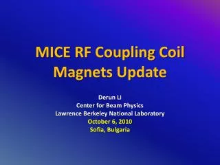
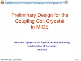
Preliminary Design for the Coupling Coil Cryostat in MICE. Institute of Cryogenics and Superconductivity Technology Harbin Institute of Technology P.R.China.

E N D
Preliminary Design for the Coupling Coil Cryostat in MICE Institute of Cryogenics and Superconductivity Technology Harbin Institute of Technology P.R.China
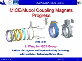
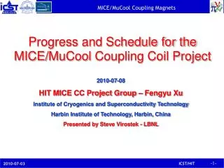
According to the “Technical Specification on MICE Coupling Solenoid Magnet Fabrication, Assembly, Test and Shipping”, ICST/HIT carried out the preliminary engineering design on the coupling magnet cryomodule since this August. The following persons have been involved in the current design in ICST. Dr. Lin X.Jia, Professor Dr. Li Wang, Professor Mr. C.S.Liu, Engineer Mr. G. Hang, Engineer H.Wu, Ph.D. candidate, numerical calculation L.K.Li, M.S. candidate, numerical calculation The detailed calculations and numerical simulations are going on.
The presented include: • Process flow diagram • Cryostat • Helium vessel • Self-centered supports • Current leads
Cryo-cooler He compressor GHe storage tank LHe dewar Vacuum pumping Coupling magnet cryomodule Flow Diagram
The precooling or test system is composed of • LHe dewar (250L, 500L available in ICST ) • LN2 dewar (if necessary, 200L, 500L available in ICST ) • GHe storage tank (5m3, 10m3 available in ICST ) • He compressor • Transfer lines • Safety device (relief valves, rupture disc etc.) • Valves • Vacuum pumping system (available in ICST ) • Cooling water system (available in ICST )
Cryostat • The cryostat is composed of • Vacuum chamber made of stainless steel • Radiation shield made of annealed OFHC copper • Helium vessel made of stainless steel or 6061-T6 Aluminum • Coil assembly consisting of NbTi/Cu SC conductors, bobbin, ground insulation, epoxy and support cylinder (or banding) • Copper leads + HTS leads • Supports • LHe condenser • Cryo-cooler • Piping • Bayonets and fittings • Feedthroughs for temperature sensors, heater, level meter, voltage taps etc. • Instrumentation including temperature sensors, heater, level meter, pressure transducers etc. • MLI insulations and electrical insulations
Feedthrough Cryo-cooler VHe piping Cold-down return piping Supports Helium vessel Vacuum vessel Shields LHe piping Cold-down supply piping Vacuum port
Piping to relief device 1st stage cold head Bayonet Copper lead 2nd stage cold head Flexible Cu strap HTS lead Condenser Supports Eddy current interrupt slot
Up to the magnetic field distribution, the location of HTS leads and cryocooler will be changed.
Support cylinder Coil He vessel Bobbin
Helium Vessel Option A Option B A separated vessel to contain the coil assembly Coil is cooled either through conduction or directly by LHe Complex structure and assembly Directly made of coil bobbin, end plates and cover cylinder Coil is cooled through conduction Simple structure, but thick Al material needed
SS vessel wall Liquid helium 4.2K SS Support cylinder Ground insulation Coil Al Bobbin Two cooling schemes for Option B: Helium vessel is made of stainless steel. The coil is cooled through conduction by liquid helium. SS thickness=15mm △Tcoil<0.1K Temperature distribution q-radiation=0.2W/m2
4.2K The coil is cooled directly by liquid helium. q-radiation=0.2W/m2 △Tcoil<0.066K
Helium passage Support cylinder Coil Bobbin Helium passage
SS vessel wall Liquid helium 4.2K Al Support cylinder Ground insulation Coil Al Bobbin The coil is cooled through conduction by liquid helium. q-radiation=0.2W/m2 △Tcoil<0.1K
4.2K The coil is cooled directly by liquid helium. q-radiation=0.2W/m2 △Tcoil<0.066K
Stress analysis for Option B:to consider the radial, longitudinal and gravity forces as well as the 4 bara pressure inside. 15mm SS in thickness Supports
To only consider the 4 bara pressure inside for SS helium vessel.
Option A:directly made of coil bobbin, end plates and cover cylinder 4.2K 6061-T6 Al 6061-T6 Al The coil is cooled through conduction by liquid helium. q-radiation=0.2W/m2 △Tcoil=0.04K Al thickness=25mm
25mm Al in thickness Supports Stress analysis for Option A:to consider the radial, longitudinal and gravity forces as well as the 4 bara pressure inside.
To only consider the 4 bara pressure inside for Al helium vessel.
16mmx12.5mm, 175mmx2 G-10 band SS ~50K Supports without 50K intercept
~50K Supports with 50K intercept
Heat loads from cold mass supports Supports with 50K intercept Supports without 50K intercept The structure and dimensions of the supports need to be further optimized.
Copper lead HTS lead Current leads The current lead for coupling coil consists of a conduction-cooled copper lead that carries current from room temperature to intercept temperature (the first stage of cryocooler) and a HTS lead that carries current from the intercept to the coil.
TH I Q z dz Q+dQ TL Design for Copper current leads Energy equation: (1) (2) (3) Assuming: The optimized heat flow into the cold end of the lead: (4a) (5) (6a)
To apply Wiedemann-Franz law for most metal and alloy, (4b) (6b)
For I=250A TL=50K, Qopt=11.563W TL=60K, Qopt=11.49W For I=220A TL=50K, Qopt=10.176W TL=60K, Qopt=10.112W
Parameters used for numerical simulation of the copper lead by FLUENT I=250A, D=8mm, L=0.4m, Q=14.27W
Temperature distribution along the copper lead at I=300A, D=8mm, L=0.4m Q=15.245W
Temperature distribution along the copper lead at I=500A, D=8mm, L=0.4m T-warm-end>300K
Temperature distribution along the copper lead at I=300A, D=8mm, L=0.7m T-warm-end>300K
Parameters of HTS Current Leads The nominal current for the HTS lead is 220A, and it must be capable of carrying 500A when the high-temperature end of the lead is nominally at 60K and at 1.5T. *Data from Sumitomo Electric Superconducting tubes of BiPbSrCaCuO (Bi-2223 phase) ceramics with silver covered ends of a low contact resistance are suitable for current leads effectively reducing heat leak into superconducting magnets. For better mechanical protection the leads may be encased in metal or G-10 tubing.
Heat loads from the current leads Copper leads (300K-50K) HTS leads (50K-4.2K) Since the performance of HTS leads will be greatly influenced by the magnetic field, we should consider it while to select the commercial leads.
Winding Process Winding procedure and materials to be used need further detailed discussion.
The detailed further calculations and analyses are going on provided no change on the coil design such as the coil itself and its quench protection, vacuum vessel, supports, helium condenser, piping, safety device, instruments, interface to RF cavity module and so on.
ICST contribution summary up to date • Two professors (one half time and one quarter time) • Two engineers (one and a half time) • Two graduates (full time) • ICST future possible contributions (year’07) • Research fund $10k • Three professors (two half time and one quarter time) • Four engineers (full time) • Three graduates (full time) • Four mechanical/cryogenic technicians (full time)