Download
1 / 23
230 likes | 464 Views
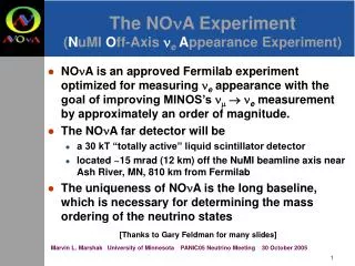
The NO n A Experiment. Survey of the NOvA Near Detector at Fermilab Babatunde O’Sheg Oshinowo Horst Friedsam Fermi National Accelerator Laboratory Batavia, Illinois. Gary Feldman Harvard University. The NOvA Experiment. NO A: N uMI O ff-Axis n e A ppearance Experiment

E N D
The NOnA Experiment Survey of the NOvA Near Detector at Fermilab Babatunde O’Sheg Oshinowo Horst Friedsam Fermi National Accelerator Laboratory Batavia, Illinois Gary Feldman Harvard University
The NOvA Experiment NOA: NuMI Off-Axis neAppearance Experiment ne= electron neutrino • NOvA is a second-generation experiment on the NuMI beamline • The NOvA project also includes accelerator upgrades to bring the NuMI beam intensity from 400 kW to 700 kW • Main physics goal will be the study of • nmne oscillations • Uses two detectors: • Far Detector in Ash River, Minnesota • Near Detector at Fermilab • Run for 6 years
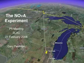
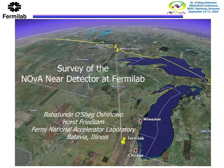
Far Detector Site • This site is at 810 km from Fermilab, 12 km off-axis • The Ash River site is the farthest available site from Fermilab in the U.S. along the NuMI beamline
Near Detector Cavern The Near Detector will be placed underground on the Fermilab site 1 km off-axis, in a cavern adjacent to the MINOS access tunnel
What is NOvA? • NOvA is: • • A 15 kTon Far Detector sited • 13.6 mrad off the NuMI beam axis • at a distance of 810 km at a • distance of 12 km • • A 222 ton Near Detector identical • to the far detector sited 13.6 mrad • off the NuMI beam axis at a • distance of 1 km • An 84 Ton IPND (Integration Prototype • Near Detector)identical to the Near • Detector sited on the surface 107 mrad • off the NuMI beam axis in the NOvA • Near Detector Surface Building
NOvA Detector PVC Extrusion • The NOvA detectors are constructed from • planes of PVC modules • The NOvA detector module forms the base unit for the detector • Extrusions have a cellular structure, with 16 isolated cells per extrusion • Each module is made from two 16 cell high reflectivity PVC extrusions bonded into a single 32 cell module • L = 15.7 m for Far Detector • L = 4.2 m for Near Detector • Modules capped by a Manifold and an End Plate/Cap to contain the liquid scintillator • Vertical plane = Two extrusion modules • (64 cells wide) • Horizontal plane three extrusion modules (96 cells high) PVC Module = Module Plane
NOvA Block • The NOvA detector is constructed from alternating layers (planes) of vertical and horizontal PVC extrusion modules, connected together by glue between layers. • The basic structural unit of the detector is a subassembly of 31 planes of PVC extrusion modules called a Block • With an odd number of planes per block, there are two possible configurations: • Vertical block (V) when the first and last planes are vertical modules • V = v0h1v2h3v4h5v6h7v8h9v10 ….. v20h21v22h23v24h25v26h27v28h29v30 • Horizontal block (H) when the first and last planes are horizontal modules • H = h0v1h2v3h4v5h6v7h8v9h10 ….. h20v21h22v23h24v25h26v27h28v29h30 • number of planes is counted from 0 through 30
Far Detector • The Far Detector (FD) consists of 33 blocks 20 “V” and 13 “H" blocks: • FD V0H1V2H3V4 V5……..V25H26V27H28V29 V30H31V32 • where the number of blocks is counted from 0 through 32. • The total number of planes in the far detector is 1003 (505 vertical, 498 horizontal), 32 blocks with 31 planes each and 1 block with 11 planes. • Twelve (12) extrusion modules get placed side by side on a flat assembly table to form one plane of the far detector O’Sheg
Integration Prototype Near Detector (IPND) • Constructing prototype detector to run on the surface near NOvA Near Detector Surface Building • The IPND consists of 4 Blocks: • IPND V0H1V2H3 • where the number of blocks is counted from 0 through 5 • 2.9 m wide • 4.2 m tall • 8.4 m long 4 blocks = IPND
NOvA Near Detector • The Near Detector (ND) consists of 6 Blocks: • ND V0H1V2H3V4V5 • where the number of blocks is counted from 0 through 5 • 2.9 m wide • 4.2 m tall • 14.3 m long
Survey of NOvA Near Detector • Establish a precision horizontal and vertical control network for positioning the Near Detector in the Local Tunnel Coordinate System (LTCS) • The network consists of both horizontal and vertical networks using several wall monuments and pass points in the NOvA Near Detector Surface Building (NDSB) • Tie the new NDSB horizontal and vertical network was tied to the existing surface network used for the NuMI project • Magnet Rings used as Fiducials • Fiducials are glued with 24-Hour Epoxy Magnet Ring (19 mm OD, 12 mm ID and 10 mm thick N40 super magnet)
Survey Methodology • All Survey for the near detector was done with: • An API Tracker3Laser Tracker and Spatial AnalyzerTM • - 3-D Accuracy : Accuracy of a Coordinate: ± 5 μm/m • - Interferometer: Accuracy of IFM: 1 μm/m • - ADM: Accuracy ±15 μm or 1.5 μm/m (whichever is greater) • Leica HDS6100 Laser Scanner system and its associated software • - Full 360° x 310° field-of-view and extended • range of up to 79 m. • - Accuracy of single measurement is: • Position 5 mm • 1 m to 25 m range; 9 mm to 50 m range • Overall Survey Tolerance: • Relative 2 mm (Horizontal) edge to edge; • Relative 0.75 mm or better (Vertical) between adjacent pieces • Angular tolerance of ± 2 mm/15.7 m = ± 0.13 mrad
Block Fiducialization • Total of 24 fiducials are used for each block, 18 on the model extrusions and 6 on the blue steel base plate. • There 9 fiducials on the extrusions at about the first, middle and last planes and 3 on the base plate on the east side of the block • The same number of fiducials is on the west side. • Magnet Rings used as Fiducials
Block Referencing • The fiducialized blocks were referenced using the Laser Tracker in a local magnet coordinate system the in MINOS Service Building prior to installation in the NOvA Near Detector Surface Building • Blocks with Fiducials were Referenced in two parts: • - Reference Part 1: Block in Prone Position • - Reference Part 2: Block in Upright Position
Part 1: Block in Prone Position • Measured the local control points in the MINOS Service Building • Measured all 24 Block fiducials • Groove measurements on Block were made at specified locations by placing the SMR where the horizontal module grooves intersect the extreme end of the vertical plane • The bottom of the SMR sat in the horizontal groove while the one side of the SMR touched the vertical plane
Part 2: Block in Upright Position • Measured the local control points in the MINOS Service Building • Measured all 24 Block fiducials • Performed best-fit transformations to transform all the Prone Position measurements into the Upright Position measurements. • Measured the upstream and downstream surfaces of the Block. This was done with 8 scans along the edges of each module. • Computed plane fit for each surface and the vector differences to the corresponding measurements • Reported vectors graphically.
Block Corner Positions • Block is defined by the 8 Corners • computed from plane fits to all • measurements • Referencing Methods used • Plane Fits • Plane-Plane Intersections • 3-Plane Intersections • Line Fits • Line-Line Intersections
Block Data Reporting • Graphical Output of Roll, Pitch, Yaw Offsets dX, dY, dZ • Able to easily identify the missing groove measurements and/or outliers due to too much glue • Perform best-fit transformations to transform all the Ideal position locations [xI, yI, zI] generated for each module into the Measurement coordinate system [xM, yM, zM]
IPND Assembly • Blocks are moved into the NOvA Near • Detector Building for assembly • 5 out of 6 Blocks have been assembled Five Blocks Assembled in NOvA Building
Challenges • Excessive Glue in the Grooves • Residual Black Paint in the Groove and on the Vertical Module • RTV Silicone Adhesive on the Vertical Module
Status NOvA Near Detector • IPND installation is completed. • No Liquid Scincillator fill yet. • 6th Block to be referenced and installed by beginning of October, 2010 • Muon Catcher to be referenced and installed by mid-October, 2010 • Survey of the 6 Blocks and Muon Catcher in the NOvA Near Detector Building by end of October, 2010 • 4th detector block ready to take data (IPND) by beginning of November, 2010 • Near detector ready to take data by mid-November, 2010 • Survey of the 6 Blocks in the MINOS Tunnel by Fall of 2011 Five Blocks Assembled in NOvA Building
Conclusions • The survey methodology used has been presented • The NOvA Near Detector survey is in progress
Acknowledgment • I would like to thank • Alignment and Metrology Group members who participated in the NOvA Near Detector project, especially Gary Crutcher who did a lot of the data processing • Dr. Pat Lukens and Dr. Ting Miao - • NOvA Collaboration Danke Frage?