Download
1 / 22
220 likes | 397 Views
J.G. Schepers, K. Boorsma C. Kim, T. Cho. IEA Task 29 ‘Mexnext’: Analysis of Mexico measurements: Detailed aerodynamic measurements on a 4.5 m diameter rotor placed in the large German Dutch Wind Tunnel DNW. Content. Mexico experiment/Mexnext

E N D
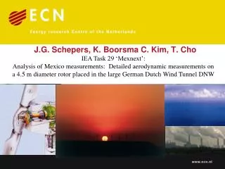
J.G. Schepers, K. Boorsma C. Kim, T. Cho IEA Task 29 ‘Mexnext’: Analysis of Mexico measurements: Detailed aerodynamic measurements on a 4.5 m diameter rotor placed in the large German Dutch Wind Tunnel DNW
Content • Mexico experiment/Mexnext • Rotor speed dependancy on aerodynamic coefficients • Comparison Mexico results with KARI results • Flow non-uniformities due to finite number of blades; Tip (and root) correction • Comparison between calculations and measurements • Relation between rotor loads and flow field
EU project Mexico Model rotor EXperiments In COntrolled conditions 1) • 2001-2006 • Measurements in German Dutch Wind tunnel, DNW • North East Polderin Netherlands • Open test section:9.5 x 9.5 m2 • Diameter of rotor:4.5 m • Fast pressure measurements at 5 positions (25%, 35%, 60%, 82% and 92% span) along the blade and blade root bending moment measurements • Tower bottom load measurements • Particle Image Velocimetry (PIV): Quantitative flow visualisation 1) Participants: see http://www.ecn.nl/nl/units/wind/rd-programma/aerodynamica/projects/mexico/
MexNext: Goal and Results • Goal: A joint effort in which the Mexico measurements (together with the previously made NASA-Ames measurements) are evaluated. • Validated and improved aerodynamic models: • General BEM modelling • Free vortex wake models • CFD blade flow and near wake flow • Yawed flow models • Dynamic Inflow models • Instationary airfoil aerodynamics • General inflow modelling (non-uniformity between blades) • 3D models (including tip effects) • Results (i.e. the insights on accuracy of different models, and the recommendations/descriptions for model improvement) will be made public
MexNext: Participants • Participation from the following research institutes from 11 different countries: • Canada (École de technologie supérieur, Montreal (ETS), University of Victoria (UVic)) • Denmark(DTU-RISO/DTU(Mek)) • Germany(University of Stuttgart (IAG), University of Applied Sciences, Kiel, Forwind) • Israel (Israel Institute of Technology (Technion)) • Japan (Mie University/National Institute of Advanced Industrial Science) • Korea((Korea Institute of Energy Research (Kier) and Korea Aerospace Research Institute (Kari)) • Netherlands(Energy Research Center of the Netherlands (ECN), University of Delft (TUDelft), Technical University of Twente) • Norway (Institute for Energy Technology/Norwegian University of Science and Technology (IFE/NTNU) ) • Spain(Renewable Energy National Centre of Spain (CENER) and National Institute for Aerospace Technology, INTA) • Sweden(Royal Institute of Technology/University of Gotland (KTH/HGO)) • USA (National Renewable Energy Laboratory (NREL)) • Industrial participation from Suzlon Blade Technology (NL office of Suzlon) and Wind Guard (Germany)
Content • Mexico experiment/Mexnext • Rotor speed dependancy on aerodynamic coefficients • Comparison Mexico results with KARI results • Flow non-uniformities due to finite number of blades; Tip (and root) correction • Comparison between calculations and measurements • Relation between rotor loads and flow field
CDax(l) for two rotor speeds • Good agreement between pressure and balance axial force Axial force reliable • No rotor speed dependancy on axial force coefficient
Korean daughter of the Mexico rotor Mexico, D=4.5 m KARI D=2 m Tunnel: 5 x 3.75m Tunnel: 9.5x9.5m 8
KARI: Torque coefficientsat 5 rotational speeds KARI vs Mexico: CP at two tip speeds stall 9
Content • Mexico experiment/Mexnext • Rotor speed dependancy on aerodynamic coefficients • Comparison Mexico results with KARI results • Flow non-uniformities due to finite number of blades; Tip (and root) correction • Comparison between calculations and measurements • Relation between rotor loads and flow field
Animation of Fluent calculated flow field: Uniform flow upstream and downstream of rotor, non-uniformities in rotor plane due to finite number of blades
Prandtl tip correction (F), correction for flow non-uniformities due to finite number of blades • Finite number of blades: Flow in rotor plane is not uniform due to discrete vortices (not a continuous distribution) • These effects are covered by the tip correction factor F, such that • a is induction factor at the position of the blade • aF is annulus averaged induction • Resulting BEM equation • Tip correction factor • F according to Prandtl use local a
Basic idea derivation Prandtl tip correction (1919) • Simplifiedvortex wake model • Vortexplanesmoving downstream withVd at mutualdistance d=(2pr/B) sin Ftip(i.e. the distance over which the vortex ‘travelled’ untilnextblade passes) • F = (2/p)arccos(e-(B (R-r)/2rsinF)) • Question: Is itpossible to usenowadays a more physical (numerical) free vortex wakemethod to assess F From wind energy handbook: Burton, Sharpe, Jenkins, Bossanyi
Comparison between the azimuthallyaveraged velocities and local velocities at the blade • Mexico vs AWSM (free wake lifting line code) • Very good agreement betweenmeasured and AWSM azimuthally averaged values • Tip vortex released inboard • Local velocity does not approach the averaged velocity at inboard positions (slight off-set in bladeposition?) Azimuthal averaged and local velocities (Mexico vs AWSM)
Prandtl and AWSM tip loss correction 15 m/s 10 m/s 24 m/s • Deviation near very tip (cut-off radius for viscous core) • Tip speed ratio (inflow angle) dependancy might be improved? • ‘Tip’ loss factor also often used as ‘root’ loss factor: What is the root radius? • Location of maximum chord seems to be a good choice
Content • Mexico experiment/Mexnext • Rotor speed dependancy on aerodynamic coefficients • Comparison Mexico results with KARI results • Flow non-uniformities due to finite number of blades; Tip (and root) correction • Comparison between calculations and measurements • Relation between rotor loads and flow field
Calculations done with cylindrical vortex sheet model 1) based on given CDax CDax = 4a(1-a) a∞ = 2arotor plane CDax =0.89(a=1/3)(as expected at design conditions) PIV measured and calculated speed decay as function of x at 61% and 82% span for Vtunnel = 15 m/s and q = -2.3 degrees (design conditions) Generally speaking a good agreement is found IF CDax = 0.89 1) H. Snel and J.G. Schepers: Joint Investigation of Dynamic Inflow Effects and Implementation of an Engineering Method, ECN-C-94-107, 1994
But Cdax is not 0.89!! 6,67 Cdax ~0.72 only! • Possible explanations: • Wrong axial force measurement?No, we find the same CDax (l=6.67) from pressure and balance and for 324.5 and 424.5 rpm • Tunnel effects: Very unlikely! • Can it really be that the axial momentum relation (i.e. the foundation of every wind turbine design code) is wrong???????
Some conclusions from Mexnext • A large number of studies are carried in Mexnext, results can be found on www.mexnext.org • Rotor speed dependancy on aerodynamic coefficients is very small for the Mexico experiment but some dependancy is seen on the smaller KARI rotor at low rotational speeds near stall • Indications have been found that tip speed ratio dependancy in Prandtl tip loss factor might be improved.Position of maximum chord gives a good estimate for the root radius in the Prandtl root correction • In the Mexico project the flow details around the rotor have been measured. These are predicted very well under the assumption that the Cdax is the expected value (where the measurements at two rotational speeds and done with two independent measurement techniques, show it is not…)
We need a (convincing) explanation for the non-understood relation between loads and velocities! MEXNEXT AWARD Jury: Gerard Schepers and Koen Boorsma
Acknowledgements • Co-Authors (Koen Boorsma, Cheolwan Kim and Tae-Wan Cho) • Mexnext participants • IEA Executive Committee