Download
1 / 34
340 likes | 535 Views
RPC PAC muon trigger of the CMS detector. Physics at Future Colliders, January 11, 2006. CMS - C ompact M uon S olenoid. Total weight : 12 500 t Overall diameter : 15 m Overall length : 21.6 m Magnetic field : 4 Tesla. Need for trigger. LHC. 2 2875 proton bunches

E N D
RPC PAC muon trigger of the CMS detector Physics at Future Colliders, January 11, 2006
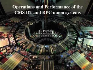
CMS - Compact Muon Solenoid Total weight : 12 500 t Overall diameter : 15 m Overall length : 21.6 m Magnetic field : 4 Tesla Karol Buńkowski, Warsaw University
Need for trigger LHC 2 2875 proton bunches 1011 protons / bunch E = 7 TeV per proton 40 millions of bunch crossing /s ~ 20 proton-proton interactions each 25 ns, resulting in hundredths of particles Detector response ~1 MByte of data (after zero suppression) 4 1013 Bytes (4000 GB) / s Not possible to record!!! Karol Buńkowski, Warsaw University
Need for trigger (2) But most of events is not very interesting (classical physic) Signature: low transverse momentum (pT) We are looking for very rare events in which heavy particles were produced Decay into high energy objects (hardronic jets, leptons, photons) Signature: high transverse momentum (pT) Karol Buńkowski, Warsaw University
CMS/LHC Trigger Physics • Standard model Higgs (high luminosity) • • H (80 GeV) • • H (120 GeV) Z Z* (4 leptons) • • H (>500 GeV) leptons ( +'s) • • H (< 2MW Associated t or W or Z) b b (lepton + X) • SUSY Higgs (low luminosity) • • (standard model Higgs like channels) • • h, H, A (lepton + X) or • • A Z h ; h bb (lepton + X) • • p p t t X; t H+ b; H+ ; t lepton + X; X • SUSY sparticle searches (low luminosity) • • MSSM sparticle LSP (Missing Et) + n jets • • MSSM sparticle Same sign dileptons + X • Other new particles • • Z' dileptons • • Leptoquarks: dileptons • Top physics (low luminosity) • • t lepton + X • • t multijets • Bottom physics (low luminosity) • •b lepton + X • •b ks (leptons + X) • QCD • • Low luminosity 100 GeV jets • • High luminosity 200 GeV jets L1 Trigger objects requirements: • High luminosity (1034 cm-2s-1): e/ (30 GeV), ee/ (15 GeV) (20 GeV), (5 GeV) missing ET (100 GeV), jets (200 GeV) • Low luminosity (1033 cm-2s-1): e/ (15 GeV), ee/ (10 GeV) (14 GeV), (3 GeV) missing Et (50 GeV) jets (100 GeV) Karol Buńkowski, Warsaw University
Trigger System record reject Evaluates the data of every event and decides whether record the event data to the mass storage or reject it Karol Buńkowski, Warsaw University
CMS Trigger and Data Acquisition System • Level 1 Trigger • Custom electronic • @ 40 MHz • every event is analyzed • pipeline processing – total latency 3.2 s, including ~2 s for data transmission Output ≤ 100 kHz Readout buffers 128 event deep = 3.2 s • Event Builder • switching network • (512 to 512 ports) • total throughput of approximately 500 Gbit/s • High level triggers • Farm of ~1000 commercial PCs running data selection algorithms – effectively on-line data analysis • Reduces rate from 100 kHz to 100 Hz, for storage on tape Karol Buńkowski, Warsaw University
CMS Trigger overview Karol Buńkowski, Warsaw University
Overview of Level 1 Trigger Trigger subsystems search for trigger objects, rank them and sort Applies thresholds, depending on trigger objects localization and coincidence Karol Buńkowski, Warsaw University
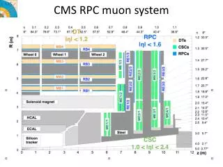
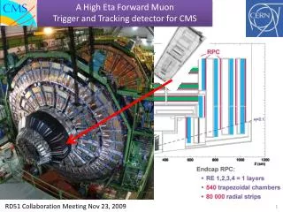
Muon Trigger Overview Drift Tubes (Barrel) Cathode Strip Chambers (endcaps) Resistive Plate Chambers (barrel & endcaps) Karol Buńkowski, Warsaw University
isolator graphite - bakelite readout strips + + - HV HV RPC - Resistive Plate Chambers Gaseous, fast detectors, optimized for muons measurements • Gas gap thickness: 2 mm • Readout Strips: pitch: 0.5 – 4 cm, length: 20 -100 cm • High Voltage ~ 9.5 kV • Gas mixture: 96.2% C2H2F4, 3.5% isoC4H10, 0.3% SF6 • Time resolution ~1 ns • Efficiency> 95% • Noise~5 Hz cm2 Karol Buńkowski, Warsaw University
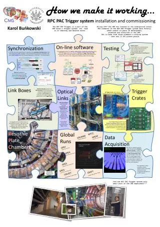
Link Board Link Board Link Board Synchronization Unit & LMUX FEB FEB FEB FEB FEB FEB RPC PAC Muon Triggeroverview Detector Counting room Control & diagnostic LVDS cables Ghost Buster & Sorter Trigger Board GB & Sorter SYNCH. & LDMUX PAC Optic Links 90 m @ 1.6 GHz 1732fibers PAC 1640 Link Boards in 136Boxes, Steered byControl Boards To theGlobal Muon Trigger PAC Data Concentrator Card DAQ 108 Trigger Boards in 12 Trigger Crates Data transmission @ 320 MHz To DAQ Resistive Plate Chambers Up to 6 layers of detectors. Karol Buńkowski, Warsaw University
Preproduction versions of boards are tested now! Trigger Board Link Board and Trigger Board Karol Buńkowski, Warsaw University
RPC PAC Muon Trigger The system was proposed and designed by Warsaw CMS group Participants: Chambers: Italy, CERN, Korea, Pakistan, China, Bulgaria Electronic: Poland (Warsaw), Italy, Finland Karol Buńkowski, Warsaw University
System complexity • 2000 chambers of different shape and construction • 165 000 strips – 1 bit electronic channels • ~15 types of electronic boards • ~2 000 pieces of electronic boards • Synchronous system, working @ 40 MHz • Most boards programmable • Most boards controlled by computers • Kilometers of cables (electrical and optical) Karol Buńkowski, Warsaw University
Tasks overview • Chambers production and tests • Design, production and tests of electronic boards • Development and tests of FPGA firmware • Tests of radiation immunity of electronics components • Configuration, control, monitoring and diagnostic: • distributed, multithread computer system • data bases: equipment, configuration, condition • real-time system performance analysis • Synchronization: bunch crossing assignment, data stream alignment • Trigger algorithms development and optimization • Trigger simulation Karol Buńkowski, Warsaw University
B=4T B=2T Magnetic filed configuration RPC strips layout plane (along the beam line) R- plane (perpendicular to the beam line) To measure the transverse momentum R- coordinate must be precisely determined Karol Buńkowski, Warsaw University
Magnetic filed configuration RPC strips layout Endcap Disc Barrel Wheels Schematic drawings 1152 strips in each layer (disc) one strip = 0.3125˚ Karol Buńkowski, Warsaw University
RPC Strips segmentation Karol Buńkowski, Warsaw University
3/4 RPC Trigger Algorithm: Pattern Comparator (PAC) • Chamber signals are compared to • predefined patterns of muon tracks • Required coincidence of hits layers: • Barrel: 6/6 or 5/6 or 4/6 or 3/4inner layers • Endcap: 4/4 or 3/4 layers • Fit pattern gives track’s • transverse momentum (pT) and sign • Level of coincidence defines • the reconstruction quality RPC Layers In case of algorithm for 6 layers 22 AND functions have to be detected for every pattern! Very complicated logic Karol Buńkowski, Warsaw University
FPGA technology overview Field Programmable Gate Array – programmable chip logic functions generator – 16 bit memory Carry and control logic, gates, MUX, etc. Synchronization to clock Look -up Table Flip-Flop Programmable interconnection lines Block RAM Input-output logic Karol Buńkowski, Warsaw University
FPGA technology overview Modern FPGA e.g. Altera Stratix II (EP2S90F1020C3): • 72768 LUTs • 4.5M of RAM bits (in block of different sizes) • 902 user I/O pins • DSP blocks (Digital Signal Processing), embedded multipliers The logic is programmed inVHDL (Very High Speed Integrated Circuits Hardware Description Language) Karol Buńkowski, Warsaw University
Improved PAC Algorithm - I 1. Patterns with the same pTcode and sign are grouped together Karol Buńkowski, Warsaw University
OR . Detecting planes without hits OR . OR . OR . OR . quality Improved PAC Algorithm - II 2. Detect planes without hits for every patterns group Karol Buńkowski, Warsaw University
OR . OR . OR . OR . OR . Improved PAC Algorithm - III 3. If there was no hit in one or two planes, set all strips of these planes to 1 Detecting planes without hits AND6 AND6 AND6 AND6 AND6 quality Karol Buńkowski, Warsaw University
OR . OR . OR . OR . OR . Improved PAC Algorithm - IV 4. For every pattern the coincidence of 6 planes is required Detecting planes without hits AND6 AND6 AND6 AND6 AND6 quality Karol Buńkowski, Warsaw University
OR . OR . OR . OR . OR . Improved PAC Algorithm - V 5. Sort the found tracks candidates Detecting planes without hits AND6 AND6 AND6 AND6 AND6 AND6 AND6 AND6 AND6 AND6 AND6 quality Finding pattern with best quality and biggest code Karol Buńkowski, Warsaw University
OR . OR . OR . OR . OR . Improved PAC Algorithm - VI Note: muon hits not fit to any patterns or noise hit occurred in plane without muon hit Detecting planes without hits None pattern fits to hits AND6 AND6 AND6 AND6 AND6 quality Small loss in efficiency and small increase of ghost rate Karol Buńkowski, Warsaw University
Pac Chip Implementation in FPGA • Implemented in parameterized VHDL code, including configuration file defining • PAC units inputs, • quality definition • and patterns One PAC chip (1of 396 in whole system): • Pattern Comparator algorithm • Input data decompression and synchronization • Data distribution to PAC units Compilation results for PAC chip from Tower 0 containing 14 252 patterns defined on 6 planes: Device: Altera Stratix IIEP2S90F1020C3 – 72768 LUTs : • LUTs Used: 42 064 (57 %) • Frequency > 45 MHz • Compilation Time ~ 2 hours Karol Buńkowski, Warsaw University
Vertex muon rate RPC PAC trigger performance • L1 Trigger requirements: • Find as many as possible of trigger objects Maximization of efficiency above threshold • Keep output rate below required level In case of RPC PAC trigger these requirements are realized by: • During patterns generation (from the simulated tracks) the value of pT is assigned to patterns in a way assuring > 90% efficiency • PAC algorithm selects the pattern with best quality and highest pT Muons reconstructed with pT > 20 GeV Only 4% of accepted muons has vertex pT above threshold Rate per bin [Hz] Caution: bin size varies! Karol Buńkowski, Warsaw University
> 6 Trigger performance simulation - strategy and conditions Simulation conditions • Luminosity: 1034 • Cluster size distribution • Chambers noise 5 Hz/cm2 • Chambers efficiency 95% • Neutron background: nominal level × 0.6 What we are mostly interested in?: • Trigger efficiency (especially for high pT muons) • Trigger rate vs. pT threshold • False triggers and ghosts rate Muon sample: • single muons originating from vertex, • flat distribution in pT (for rate studies pT spectrum re-weighted with rate parameterization) • flat distribution in • 1.83 millions of events (positive and negative muons), Karol Buńkowski, Warsaw University
Trigger efficiency curves Endcap region (0.93 < < 2.1, trigger tower 7-6) Barrel region ( < 0.93, trigger tower 0-6) Karol Buńkowski, Warsaw University
Trigger Rate (whole detector) ~25 kHz @ pT threshold 20 GeV Trigger rate Vertex muon rate Karol Buńkowski, Warsaw University
Then maybe we will find the event with 4 high-energy muons… Conclusions LHC and CMS (including RPC PAC trigger) should start working on the first half of 2007… And this could indicates, that we are observing HIGGS! Karol Buńkowski, Warsaw University