Download
1 / 21
3.71k likes | 10.74k Views
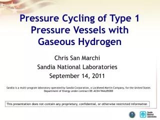
INTRODUCTION TO PRESSURE VESSELS. PRESSURE VESSELS. Pressure vessels are the containers for fluids under high pressure. They are used in a variety of industries like Petroleum refining Chemical Power Food & beverage Pharmaceutical. TYPES OF PRESSURE VESSELS.

E N D
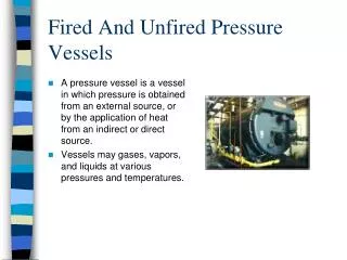
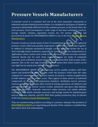
PRESSURE VESSELS • Pressure vessels are the containers for fluids under high pressure. • They are used in a variety of industries like • Petroleum refining • Chemical • Power • Food & beverage • Pharmaceutical
TYPES OF PRESSURE VESSELS There are three main types of pressure vessels in general • Horizontal Pressure Vessels • Vertical Pressure Vessels • Spherical Pressure vessels However there are some special types of Vessels like Regeneration Tower, Reactors but these names are given according to their use only.
The max. Shell length to diameter ratio for a small vertical drum is about 5 : 1 VERTICAL PRESSURE VESSEL
Constructed in a wider range of shell diameter and height. They can be relatively small in dia. and very large (e.g. 4 ft dia. And 200 ft tall distillation column. They can be very large in dia. and moderately tall (e.g. 3 ft dia. And 150 ft tall tower). Internal trays are needed for flow distribution. TALL VERTICAL TOWER
Figure shows a typical reactor vessel with a cylindrical shell. The process fluid undergoes a chemical reaction inside a reactor. This reaction is normally facilitated by the presence of a catalyst which is held in one or more catalyst beds. VERTICAL REACTOR
MAIN COMPONENTS OF PRESSURE VESSEL Following are the main components of pressure Vessels in general • Shell • Head • Nozzle • Support
SHELL • It is the primary component that contains the pressure. • Pressure vessel shells in the form of different plates are welded together to form a structure that has a common rotational axis. • Shells are either cylindrical, spherical or conical in shape.
SHELL • Horizontal drums have cylindrical shells and are constructed in a wide range of diameter and length. • The shell sections of a tall tower may be constructed of different materials, thickness and diameters due to process and phase change of process fluid. • Shell of a spherical pressure vessel is spherical as well.
HEAD • All the pressure vessels must be closed at the ends by heads (or another shell section). • Heads are typically curved rather than flat. • The reason is that curved configurations are stronger and allow the heads to be thinner, lighter and less expensive than flat heads. • Heads can also be used inside a vessel and are known as intermediate heads. • These intermediate heads are separate sections of the pressure vessels to permit different design conditions.
NOZZLE • A nozzle is a cylindrical component that penetrates into the shell or head of pressure vessel. • They are used for the following applications. • Attach piping for flow into or out of the vessel. • Attach instrument connection (level gauges, Thermowells, pressure gauges). • Provide access to the vessel interior at MANWAY. • Provide for direct attachment of other equipment items (e.g. heat exchangers).
SUPPORT • Support is used to bear all the load of pressure vessel, earthquake and wind loads. • There are different types of supports which are used depending upon the size and orientation of the pressure vessel. • It is considered to be the non-pressurized part of the vessel.
TYPES OF SUPPORTS SADDLE SUPPORT: • Horizontal drums are typically supported at two locations by saddle support. • It spreads over a large area of the shell to prevent an excessive local stress in the shell at support point. • One saddle support is anchored whereas the other is free to permit unstrained longitudinal thermal expansion of the drum.
TYPES OF SUPPORTS LEG SUPPORT: • Small vertical drums are typically supported on legs that are welded to the lower portion of the shell. • The max. ratio of support leg length to drum diameter is typically 2 : 1 • Reinforcing pads are welded to the shell first to provide additional local reinforcement and load distribution. • The number of legs depends on the drum size and loads to be carried. • Support legs are also used for Spherical pressurized storage vessels. • Cross bracing between the legs is used to absorb wind or earth quake loads.
LUG SUPPORT: Vertical pressure vessels may also be supported by lugs. The use of lugs is typically limited to pressure vessels of small and medium diameter (1 to 10 ft) Also moderate height to diameter ratios in the range of 2:1 to 5:1 The lugs are typically bolted to horizontal structural members in order to provide stability against overturning loads. TYPES OF SUPPORTS
TYPES OF SUPPORTS SKIRT SUPPORT: • Tall vertical cylindrical pressure vessels are typically supported by skirts. • A support skirt is a cylindrical shell section that is welded either to the lower portion of the vessel shell or to the bottom head (for cylindrical vessels). • The skirt is normally long enough to provide enough flexibility so that radial thermal expansion of the shell does not cause high thermal stresses at its junction with the skirt.
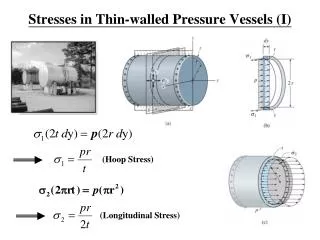
THIN WALLED PRESSURE VESSELS • Thin wall refers to a vessel having an inner-radius-to-wall-thickness ratio of “10” or more (r / t ≥ 10). • When the vessel wall is thin, the stress distribution throughout its thickness will not vary significantly, and so we will assume that it is uniform or constant. • Following this assumption, the analysis of thin walled cylindrical and spherical pressure vessel will be carried out. • In both cases, the pressure in the vessel will be considered to be the gauge pressure, since it measure the pressure above atmospheric pressure existing at inside and outside the vessel’s walls.
THIN WALLED PRESSURE VESSELS • The above analysis indicates that an element of material taken from either cylindrical or spherical pressure vessel is subjected to biaxial stress, i.e. normal stress existing in only two directions. • Actually material of the vessel is also subjected to a radial stress, σ3, which acts along a radial line. This stress has a max. value equal to the pressure p at the interior wall and decreases through the wall to zero at the exterior surface of the vessel, since the gauge pressure there is zero. • For thin walled vessels, however, the redial stress components are ignored because r / t = 10 results in σ1 & σ2 being, respectively, 5 & 10 times higher than the max. radial stress, (σ3)max = p
THIN WALLED PRESSURE VESSELS • It must be emphasized that the formula derived for thin walled pressure vessels should be used only for cases of internal pressure. • If a vessel is to be designed for external pressure as in the case of vacuum tank, or submarine, instability (buckling) of the wall may occur & stress calculations based on the formulae derived can be meaningless.