Download
1 / 18
200 likes | 403 Views
Lecture – 8 Interrupt. Outline . Introduction Handling interrupt Interrupt sources Switching interrupt Peripheral interrupts Using two interrupts Conclusions. Interrupts. Interrupts are the most used I/O technique for many systems.

E N D
Outline • Introduction • Handling interrupt • Interrupt sources • Switching interrupt • Peripheral interrupts • Using two interrupts • Conclusions
Interrupts • Interrupts are the most used I/O technique for many systems. • One problem exists with interrupts the are difficult to troubleshoot. • The ISR is the function called by an interrupt. • Each interrupting source has three control bits, IF (interrupt flag), IE (interrupt enable), and IP (interrupt priority). • The IF flag is set only if an interrupt takes effect and cleared by the program.
Handling interrupts (1) • The mechanism is very similar to CALL: • the present instruction completes. • PC (the address of the next instruction) is saved to the hardware stack • ISR is called at a fixed (by PlCarchitecture) address. • ISR operates as a subroutine (MUST not corrupt any registers/flags/bank settings/W), return (RETFIE) on completion.
Handling interrupts (2) • ISR starts at the specific address. • PC of the interrupted program is saved by hardware in a hardware stack. • STATUS register and any other registers used by ISR are to be saved by the programmer if necessary. • ISR should (1) polls status bits of valid interrupt sources; (2) serve requested; (3) clear their request bits. • Restore registers and RETIF (programmer).
Interrupt sources • Direct pin at PORT B (interruptrequest) • Change of signal at most pins of port B (interrupt on change) • Generated by built-in peripherals (e.g., timers on overflow etc) • Generated by internal watchdog timer - could be used to recover after a hardware malfunction. • Generated when the supply voltage drops below a preset level, or just recover from a power loss. Interrupts can be disabled in general, or any specific interrupt can be disabled.
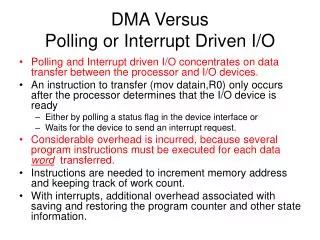
Why interrupt control is required • How it is possible to handle more than one interrupt? • What will happen if two interrupts occur at the same time? • What will happen if an interrupt occurs while the other one is being served ? • How to protect a critical code from being intrrupted (e.g. injecting a drug to a patient)? BCF INTCON, GIE critical code BSF INTCON, GIE
Interrupt control register • Interrupt flag bits get set when an interrupt condition occurs regardless of the state of its corresponding enable bit or the global enable bit, GIE (INTCON<7>).
Switching interrupts • General IE (GIE) - ensures that the ISR is not interrupted. • IE flags - allow to enable particular interrupts ONLY. • IF flags : indicate what interrupt actually happened.
Example • What event has happened?
Example • What event has happened?
Example • What event has happened?
ISR programming necessities • Initialisation: enable required interrupt, set GIE. • ISR: Clear the IF associated (if not, the same interrupt will occur straight on RETFIE). • ISR: Return using RETFIE.
Peripheral interrupts • Peripheral interrupts enable register (PIE1) • Peripheral interrupts request register (PIR1) • EE-EEPROM, A/D converter, EUSART receive buffer, comparator C2, comparator C1, oscillator fail, EUSART transmit buffer, timer 1 overflow.
Example • PIE1 • PIR1 • What event has happened?
Example • PIE1 • PIR1 • What event has happened? 16
Using two interrupts • E.g., on change and RC(receive). • Initialization of both required BSF INTCON, RBIE BSF PIE1, RCIE BSF INTCON, PEIE BSF INTCON, GIE
Summary • Interrupts allow putting away some background activities for something more important. • Microcontrollers deal with interrupts from free running peripherals and external stimuli. • They need to be enabled using lE flags, and the interrupt source can be determined using the IF flags. • The ISR is placed at a fixed address. • It must not to change anything except its dedicated variables. • Interrupts can be prioritised if more than one is enabled.