Download
1 / 24
270 likes | 433 Views
PERMEABLE DRAINAGE LAYERS IN AIRFIELD PAVEMENTS. 33 rd Annual Airports Conference March 3, 2010 – Hershey, PA Presented by: Dave Schilling, P.E. Outline. What is it? Resource Information Design Parameters Real World Examples Discussion Points Questions. What is it?. Evolution –

E N D
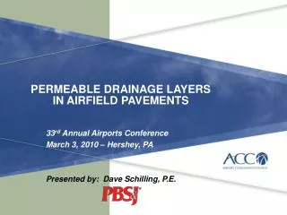
PERMEABLE DRAINAGE LAYERS IN AIRFIELD PAVEMENTS 33rd Annual Airports Conference March 3, 2010 – Hershey, PA Presented by: Dave Schilling, P.E.
Outline • What is it? • Resource Information • Design Parameters • Real World Examples • Discussion Points • Questions
What is it? • Evolution – • Good subsurface drainage has long been known to contribute to pavement life. Modern base materials, placement and higher loads have contributed to reduced permeable drainage paths • Permeable Drainage Layer – • A layer in the pavement structure that specifically designed to allow rapid horizontal drainage of water from the pavement structure
History • Commonly Used in Roadway • Pavements Since the 1980s – • Reference: NCHRP Synthesis 239, "Pavement Subsurface Drainage Systems" which is an up date of the previous Synthesis 96 with the same title. • Report found that the cost effectiveness of drainage systems is recognized by the following conclusions: • "Pavement subsurface drainage is a major factor in extending the life of a pavement." • "Although performance indicators to quantify the benefits of pavement subsurface drainage systems have not been established, use of a permeable base with a free-draining outlet system generally has demonstrated the best performance of all subsurface drainage strategies." • "The cost of pavement drainage system is high in terms of materials, construction, and maintenance, but the extended pavement life anticipated appears to make these systems cost-effective.“
Its Use FAA Advisory Circular 150/5320-5C, Change 1:
Resources FAA Advisory Circular 150/5320-5c, Change 1 Surface Drainage Design Available at: http://www.faa.gov/regulations_policies/advisory_circulars/index.cfm Status of FAA Guide Specifications?
Resources • Tri-Services (Military)- • UFC 3-230-06A • Subsurface Drainage • Available at • http://www.wbdg.org/ccb/DOD/UFC/ufc_3_230_06a.pdf • Industry – Innovative Pavement Research Foundation (IPRF) Stabilized and Drainable Base in Rigid Pavement Systems – Available at: • http://www.iprf.org/products/IPRF-01-G-002-02-1-Final%20Report.pdf
Components • Aggregate Types: • Rapid Draining Material (RDM) – permeability of 1,000 to 5,000 ft/day – usually mechanically stabilized • Open Graded Material (OGM) – permeability greater than 5,000 ft/day – usually chemically stabilized (asphalt binder or cement) • Stabilization • Usually stabilized with asphalt-binder or cement. Mechanically stabilized tends to be very sensitive to construction equipment (rutting) • Bond Breakers / Separation Layers • Filter fabrics, fine aggregate
Design Parameters • Design intent is drain rainfall that infiltrates the pavement from a 2-year, 1-hour rainfall event within a 24-hr period • Thickness design (in inches): • Where: • Infiltration coefficient (F) – assumed to be 50% per FAA / UFC recommendations for future deteriorated pavement • Rainfall Index (R) – from local IDF curves (in/hour) • Effective porosity (ne) – Recommended at 0.32 for OGM and 0.25 for RDM • Example: • (w/ R= 1.4 in/hr): • Per IPRF Report, minimum thickness is 4-inches
Design Parameters • Per FAA / UFC guidance, assumes 85% of rainfall is to be discharged within 24-hrs (assumes some water is in the layer prior to the following rain event). • Time (in days) • Where: • Effective porosity (ne) – assumed 0.32 for OGM (recommended) • Drainage Path Slope Length (L) – calculated • Slope of Drainage Path (i) – in percent (say 1.50%) • Permeability of Material (k) – in feet / day (say 2,000 ft/day) • Example: • (w/ L= 75.7-ft ) • [see next slide]
Design Parameters • Slope length – geometric length of longest drainage path. • Length (in feet): • Where: • Transverse Length (Lt ) – in feet (say 75-ft or 1/2 of runway) • Transverse slope (it ) – in percent (say 1.50%) • Longitudinal slope (ie ) – in percent (say 0.20%) • Example:
Real World Applications Memphis International Runway 18R-36L (B-747 traffic) Nashville International Runway 13-31 (B-747 traffic)
Real World Applications Detroit International Runway 3R-21L/9R-27L (B-747 traffic) East WV Regional (Martinsburg, WV) Runway 8-26 (C-5 traffic)
Real World Applications NW Arkansas Regional Runway 17-35 (B-747 traffic) Chicago – O’Hare Int’l Runway 10C-28C (B-747 traffic)
Discussion Points • Placement within a pavement structure • Per IPRF Report, there is no consensus. However, UFC / FAA design guidance is predicated on the assumption that water infiltrates from the top side. Groundwater effects are slower and generally mitigated through edge perimeter drains. • Per FAA AC 5320-5c, Change 1, Paragraph G-3.4 • Rigid pavements: “…should be placed directly beneath the concrete slab.” • Asphalt pavements: “…should be placed directly beneath the surface layer or beneath a graded, crushed aggregate base course.”
Discussion Points • Per FAA AC 150/5420-6E (sandwich layer?) • Appears to be a dated concern. Was applicable in the 50s and 60s with the advent of quick pavement strengthening due to heavier jet aircraft. Tendency was to use crushed aggregate to reduce asphalt thickness and cost however, this process trapped water. A stabilized drainage layer is designed to mitigate trapped water. • Is currently allowed by FAA Advisory Circular 150/5320-5c, Change 1
Discussion Points • Consideration as a stabilized layer? • Per FAA AC 150/5320-6e, Rigid Pavement designs with aircraft greater than 100,000-lbs require a stabilized layer. Although the drainage layer is “stabilized” with asphalt binder or cement, the support value is unknown. • Per FAA AC 150/5320-5c, Change 1, Paragraph G-3.4.1, “… the drainage layer along with any granular separation layer is considered a base layer, and structural benefit may be realized from the layers.” • Conservative estimates are to equate it to a P-209 crushed aggregate basestone although higher support values may be achievable with stabilization and meet the purposes of a stabilized layer.
Discussion Points • Bond Breakers / Separation Layers • Concern is with cement paste or pavement materials infiltrating into the drainage layer. Condition could clog drainage paths and “lock-in” pavements. IPRF Report performed field tests to determine that a layer of choke stone (3/8-inch minus) provided adequate drainage characteristics and separation. • Per FAA AC 150/5320-5c, choke stone recommended with unstabilized drainage layers. Separation layer is recommended in paragraph G-3.4.3 from migration of fines from underlying layers. Material can consist of geotextile fabrics or graded aggregate.