Download

1 / 67
670 likes | 925 Views
V8 i (SELECTseries 1) Overview: GEOPAK Focus. Derricke Gray GEOPAK Product Manager. GEOPAK V8 i (SELECTseries 1). Scheduled 12/18/2009 Certified With: MicroStation 08.11.07.xx ProjectWise 08.11.07.xx Operating System: Windows XP, Vista, Windows 7. Corridor Modeling. Menu Changes.

E N D
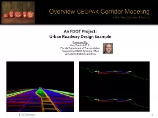
V8i (SELECTseries 1) Overview:GEOPAK Focus Derricke Gray GEOPAK Product Manager
GEOPAK V8i (SELECTseries 1) Scheduled 12/18/2009 Certified With: MicroStation 08.11.07.xx ProjectWise 08.11.07.xx Operating System: Windows XP, Vista, Windows 7
Menu Changes • Made Corridor Modeling more easily accessible via menu changes
Smart Update Prompt • Upon opening the CM application, the alignments and profiles in the GPK as well as the plan graphics elements will be checked against those residing in the ALG. If changes have been made then the following prompt will be issued:
Horizontal Filter Tolerance < Horizontal Tolerance? < Horizontal?
Vertical Filter Tolerance < Vertical Tolerance? No – then leave the point in Yes – then remove the point
ALG Viewer • Allows the user to Visualize and Delete alignments from the ALG database.
Tools > Export Profile • Allows the exporting of profiles created in Roadway Designer to be exported back to the GPK for review, printing and modification.
Tools > Draw Roadway from Template • Draws the 2D roadway graphics from a specified template.
TIN <-> DTM Conversions • In previous versions, this conversion was done via the use of XML. However, this has been replaced with an API (program) that does an internal conversion. • This greatly increases both the speed of conversion and the accuracy. • For example, a 60mb TIN will convert to a DTM in about 30 seconds.
Constraint Equations • Added the ability to specify constraint values using equations.
‘Project to Design’ Constraint • Added two new options to be used with the ‘Project to Design’ constraint.
Overlay • A complete new set of Overlay tools within Roadway Designer that give the us the following capabilities: • Cross Slope Optimization • Critical Point Assessment • Adjust, Smooth and Apply Vertical Profiles • Estimate Project Costs
Vertical Gore Tool • Creates a profile envelope of a ramp that merges into a mainline corridor. The tool produces profiles which are designed to be plotted on the profile of the ramp alignment. These profiles specify the allowable maximum and minimum elevations of the ramp vertical alignment, as well as the ideal locations to make the gore cross slope match the mainline and ramp cross slopes.
Create Surface > Components • In V8i (SELECTseries 1), we added the ability to draw the proposed surface as ‘Components’ as well as Features. • Components allow for much better detail and rendering capabilities.
Create Surface (TIN) • In previous versions of Roadway Designer, we would create an associated XML file along with the DTM surface file. Now, we go ahead and create the associated TIN file along with the DTM surface.
Corridor Symbology • When designing a project with multiple corridors, the user can now assign a different style (symbology) to each corridor for display purposes. This is especially helpful when using the Target Aliasing functionality within Roadway Designer.
Component Name Overrides • When creating surfaces, this new functionality enables the surface to close the ‘gaps’ between components with different names.
Superelevation Design Check • Added an option in the Curve Set Station Edit dialog to allow a user to check superelevation data against design standards.
Added ‘Fill’ attribute to XIN • Added a new option in the XIN file to enable the ability to ‘fill’ closed components in Roadway Designer.
XML Report Browser • Added reporting capabilities to Roadway Designer. • Superelevation Reports • Roadway Designer (.IRD) Reports • Template Library (.ITL) Reports • Milling Reports
Bentley MAP • Bentley MAP is now included with the GEOPAK Suite install.
Data Acquisition • Data Acquisition is a new set of tools that allows the user to acquire their data from multiple disparate sources. They can then combine this data seamlessly to create geometry and surface artifacts.
Survey formats: GEOPAK OUT intermediate formatGEOPAK OBS intermediate formatInRoads FWD intermediate formatMX WRW intermediate formatLandXML 1.2Field GeniusTrimble DCLeitz/Sokkia SDR2, SDR33 & SDR33-14Tripod Data Systems TDS 48, 95 & FS2Geodimeter 122, 126, 400, 500 & 600SMI versions 5, 6 & 7Topcon FC1, FC2, FC4, FC5, CR2, Propac, FC48-95 % FC5-725Leica Data Pro, Digital Level, RTA-GSI, GEOCompWildsoft GIF 2 & GIF 10Nikon DR1, DR2, 48 & 302South African TachiBookCG-Field and CG-Field plusPentax DC1 & DC1ZZeiss Rec200 and Rec 500CO OPHayesKernAASHTO SDMS
Digital Elevation Model (DEM) formats:DTEDErdas IMGSPOT DimapUSGS DEM ASCIIUSGS STDS DEMTerrain Model formats:Geopak TINInroads DTMMX FILLandXML 1.2Extract 3D graphicsLIDARXYZ (ascii)LAS (binary raw lidar files)3rd Party formats:Land Desktop LDDCaice PT4
Geometry • New Geometry tools that lead into the next generation of Civil applications. • Runs in MicroStation – not on it • Uses native feature tables (e.g. DDB) • Geometry is rules based • Geometry elements are tied together by way of relationships. • Interface is dynamic and heads up.