Download
1 / 44
460 likes | 493 Views
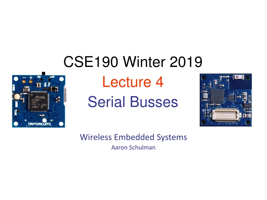
Wireless Embedded Systems Aaron Schulman. CSE190 Winter 2019 Lecture 4 Serial Busses. Serial Buses in our project. UART serial bus for sending debug messages to your development host I2C serial bus for communicating with sensors (e.g., the accelerometer)

E N D
Wireless Embedded Systems Aaron Schulman CSE190 Winter 2019 Lecture 4 Serial Busses
Serial Buses in our project • UART serial bus for sending debug messages to your development host • I2C serial bus for communicating with sensors (e.g., the accelerometer) • SPI serial bus for communicating with the Bluetooth Low Energy radio
Serial Interfaces traps & exceptions C Assembly Machine Code CPU ldr (read) str (write) Software Hardware SVC# ISA fault INT# System Buses interrupts AHB/APB Interrupts Internal & External Memory GPIO/INT Timers USART DAC/ADC Internal External EMC SPI DAC I2C ADC Input UART Output Capture Compare Interrupt
n 0 1 2 3 4 5 6 7 n+1 0 1 2 3 4 5 6 n+2 0 1 2 3 4 5 n+3 0 1 2 3 4 n+4 0 1 2 3 n+5 0 1 2 n+6 0 1 n+7 0 n+8 Simplistic View of Serial Port Operation Transmitter Receiver n n+1 7 n+2 6 7 n+3 5 6 7 n+4 4 5 6 7 n+5 3 4 5 6 7 n+6 2 3 4 5 6 7 n+7 1 2 3 4 5 6 7 n+8 0 1 2 3 4 5 6 7 Interrupt raisedwhen Receiver (Rx) is full a Byte has been received and is ready for reading Interrupt raised when Transmitter (Tx) is empty a Byte has been transmitted and next byte ready for loading
Serial Bus Interface Motivations • Motivation • Without using a lot of I/O lines • I/O lines require I/O pads which cost $$$ and size • I/O lines require PCB area which costs $$$ and size • Connect different systems together • Two embedded systems • A desktop and an embedded system • Connect different chips together in the same embedded system • MCU to peripheral • MCU to MCU • Often at relatively low data rates • But sometimes at higher data rates • So, what are our options? • Universal Synchronous/Asynchronous Receiver Transmitter • Also known as USART (pronounced: “you-sart”)
Serial Bus Design Space • Number of wires required? • Asynchronous or synchronous? • How fast can it transfer data? • Can it support more than two endpoints? • Can it support more than one master (i.e. txn initiator)? • How do we support flow control? • How does it handle errors/noise? • How far can signals travel?
UART Uses • PC serial port is a UART! • Serializes data to be sent over serial cable • De-serializes received data Slides from BYU CS 224
UART Uses • Used to be commonly used for internet access Slides from BYU CS 224
UART • Universal Asynchronous Receiver/Transmitter • Hardware that translates between parallel and serial forms • Commonly used in conjunction with communication standards such as EIA, RS-232, RS-422 or RS-485
Protocol • Each character is sent as • a logic lowstart bit • a configurable number of data bits (usually 7 or 8, sometimes 5) • an optional parity bit • one or more logic high stop bits • with a particular bit timing (“baud”)
UART Example • Send the ASCII letter ‘W’ (1010111)
UART Character Reception Slides from BYU CS 224
UART Character Reception Slides from BYU CS 224
UART Character Reception Slides from BYU CS 224
UART Character Reception • Receiver also verifies that stop bit is ‘1’ • If not, reports “framing error” to host system • New start bit can appear immediately after stop bit • Receiver will resynchronize on each start bit
Let us design a UART transmitter Slides from BYU CS 224
Transmitter/System Handshaking • System asserts Send and holds it high when it wants to send a byte • UART asserts Busy signal in response • When UART has finished transfer, UART de-asserts Busy signal • System de-asserts Send signal Slides from BYU CS 224
Transmitter Block Diagram Slides from BYU CS 224
Discussion Questions • How fast can we run a UART? • What are the limitations? • Why do we need start/stop bits? • How many data bits can be sent? • 19200 baud rate, no parity, 8 data bits, 1 stop bit
Serial Peripheral Interconnect (SPI) • Another kind of serial protocol in embedded systems (proposed by Motorola) • Four-wire protocol • SCLK — Serial Clock • MOSI/SIMO — Master Output, Slave Input • MISO/SOMI — Master Input, Slave Output • SS — Slave Select • Single master device and with one or more slave devices • Higher throughput than I2C and can do “stream transfers” • No arbitration required • But • Requires more pins • Has no hardware flow control • No slave acknowledgment (master could be talking to thin air and not even know it)
What is SPI? • Serial Bus protocol • Fast, Easy to use, Simple • Everyone supports it
SPI Basics • A communication protocol using 4 wires • Also known as a 4 wire bus • Used to communicate across small distances • Multiple Slaves, Single Master • Synchronized
SPI Capabilities • Always Full Duplex • Communicating in two directions at the same time • Transmission need not be meaningful • Multiple Mbps transmission speed • Transfers data in 4 to 16 bit characters • Multiple slaves • Daisy-chaining possible
SPI Protocol • Wires: • Master Out Slave In (MOSI) • Master In Slave Out (MISO) • System Clock (SCLK) • Slave Select 1…N • Master Set Slave Select low • Master Generates Clock • Shift registers shift in and out data
SPI Wires in Detail • MOSI – Carries data out of Master to Slave • MISO – Carries data from Slave to Master • Both signals happen for every transmission • SS_BAR – Unique line to select a slave • SCLK – Master produced clock to synchronize data transfer
SPI uses a “shift register” model of communications Master shifts out data to Slave, and shifts in data from Slave http://upload.wikimedia.org/wikipedia/commons/thumb/b/bb/SPI_8-bit_circular_transfer.svg/400px-SPI_8-bit_circular_transfer.svg.png
SPI clocking: there is no “standard way” • Four clocking “modes” • Two phases • Two polarities • Master and selected slave must be in the same mode • During transfers with slaves A and B, Master must • Configure clock to Slave A’s clock mode • Select Slave A • Do transfer • Deselect Slave A • Configure clock to Slave B’s clock mode • Select Slave B • Do transfer • Deselect Slave B • Master reconfigures clock mode on-the-fly!
SPI timing diagram Timing Diagram – Showing Clock polarities and phases http://www.maxim-ic.com.cn/images/appnotes/3078/3078Fig02.gif
SPI Pros and Cons • Pros: • Fast and easy • Fast for point-to-point connections • Easily allows streaming/Constant data inflow • No addressing/Simple to implement • Everyone supports it • Cons: • SS makes multiple slaves very complicated • No acknowledgement ability • No inherent arbitration • No flow control
I2C bus in our projects • Communication with the accelerometer • Read from the accelerometer • Pros • Simple wire connection • Two wires bus that can connect multiple peripherals with the MCU • Cons • Complexity is significantly higher
How to operate the camera? Accel I2C register 1 register 2 …. I2C MCU Springs https://www.youtube.com/watch?v=eqZgxR6eRjo
I2C Details • Two lines • Serial data line (SDA) • Serial clock line (SCL) • Only two wires for connecting multiple devices
I2C Details • Each I2C device recognized by a unique address • Each I2C device can be either a transmitter or receiver • I2C devices can be masters or slaves for a data transfer • Master (usually a microcontroller): Initiates a data transfer on the bus, generates the clock signals to permit that transfer, and terminates the transfer • Slave: Any device addressed by the master at that time
Bit Transfer on the I2C Bus • In normal data transfer, the data line only changes state when the clock is low SDA SCL Data line stable; Data valid Change of data allowed
SDA SDA SCL SCL Start Condition Stop Condition Start and Stop Conditions • A transition of the data line while the clock line is high is defined as either a start or a stop condition. • Both start and stop conditions are generated by the bus master • The bus is considered busy after a start condition, until a stop condition occurs
I2C Addressing • Each node has a unique 7 (or 10) bit address • Peripherals often have fixed and programmable address portions • Addresses starting with 0000 or 1111 have special functions:- • 0000000 Is a General Call Address • 0000001 Is a Null (CBUS) Address • 1111XXX Address Extension • 1111111 Address Extension – Next Bytes are the Actual Address
I2C-Connected System Example I2C-connected system with two microcontrollers (Source: I2C Specification, Philips)
Master-Slave Relationships • Who is the master? • master-transmitters • master-receivers • Suppose microcontroller A wants to send information to microcontroller B • A (master) addresses B (slave) • A (master-transmitter), sends data to B (slave-receiver) • A terminates the transfer. • If microcontroller A wants to receive information from microcontroller B • A (master) addresses microcontroller B (slave) • A (master-receiver) receives data from B (slave-transmitter) • A terminates the transfer • In both cases, the master (microcontroller A) generates the timing and terminates the transfer
Exercise: How fast can I2C run? • How fast can you run it? • Assumptions • 0’s are driven • 1’s are “pulled up” • Some working figures • Rp = 10 kΩ • Ccap = 100 pF • VDD = 5 V • Vin_high = 3.5 V • Recall for RC circuit • Vcap(t) = VDD(1-e-t/τ) • Where τ = RC
Exercise: Bus bit rate vs Useful data rate • An I2C “transactions” involves the following bits • <S><A6:A0><R/W><A><D7:D0><A><F> • Which of these actually carries useful data? • <S><A6:A0><R/W><A><D7:D0><A><F> • So, if a bus runs at 400 kHz • What is the clock period? • What is the data throughput (i.e. data-bits/second)? • What is the bus “efficiency”?