Download
1 / 26
260 likes | 332 Views
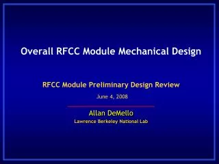
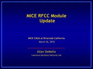
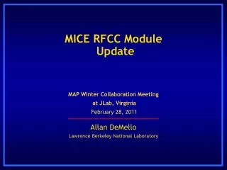
MICE RFCC Module Status. Derun Li Lawrence Berkeley National Lab. NFMCC-MCTF Collaboration Meeting LBNL, Berkeley, CA January 25, 2009. Engineering design of the RFCC module has been under way at LBNL since early last year Preliminary and final design reviews were conducted last year

E N D
MICE RFCC Module Status Derun Li Lawrence Berkeley National Lab NFMCC-MCTF Collaboration Meeting LBNL, Berkeley, CA January 25, 2009
Engineering design of the RFCC module has been under way at LBNL since early last year Preliminary and final design reviews were conducted last year Coupling coil design (MICE/MuCool) and fabrication are being provided by ICST of HIT, Harbin, China MICE cavity design is heavily based on the successful MuCool 201- MHz prototype RF cavity Fabrication techniques and post processing Engineering design of the RF cavity is complete Cavity fabrication contract to be placed soon (copper sheets arrived Berkeley last week) Significant progress on RFCC module engineering design Complete CAD model of the cavity, tuners, support and vacuum Interfaces, shipping, assembly and installation Overview Derun Li - Lawrence Berkeley National Laboratory - January 25, 2009
SC coupling Coil Curved Be window Cavity Couplers Vacuum Pump 201-MHz cavity RFCC Module Derun Li - Lawrence Berkeley National Laboratory - January 25, 2009
RFCC PDR and FDR completed during MICE CM21 and CM22 201 MHz cavity detailed design and analysis are complete Coupling coil design review completed December 2008 Qualification of three cavity fab vendors completed late last year RFP for cavity fab released by LBNL (responses due 1/30) Copper cavity material arrived LBNL last week Cavity tuner RF & structural analyses and CAD model are complete Structural analyses of cavity suspension system is complete RF coupler based on design previously developed for MuCool cavity Coupling coil interface agreed upon with ICST (working on a few details) Cavity cooling water feed-through concept has been developed Conceptual design and CAD model of module vacuum vessel, vacuum system and support structure are complete Shipping, assembly and installation concepts have been developed Progress Summary Derun Li - Lawrence Berkeley National Laboratory - January 25, 2009
Eight 201-MHz cavities & two CC magnets Eight201-MHz RF cavities RFCC modules Derun Li - Lawrence Berkeley National Laboratory - January 25, 2009
MICE RF Cavity Summary • Design based on the successful US MuCool prototype • A slight reduction in cavity diameter to raise the frequency that has been specified and analyzed • The fabrication techniques used to produce the prototype will be used to fabricate the MICE RF cavities • Final cavity design was reviewed at CM22 at RAL • Copper cavity material arrived LBNL last week • An RFP for cavity fabrication has been released, and a contract is expected to be placed next month • The first 5 cavities to be delivered by end of CY2009 Derun Li - Lawrence Berkeley National Laboratory - January 25, 2009
MICE RF Cavity Design • 3-D CST MWS parameterized RF model including ports and curved Be windows to simulate frequency, Epeak, power loss & etc. • Estimated frequency variations between cavities should be within 100 kHz (after fabrication) • Absolute frequency: 201.25-MHz 400-KHz • Approach • Slightly modify prototype cavity diameter • Target a higher cavity frequency • Tune cavities close to design frequency by deformation of cavity body (if needed) • Tuners operate in the push-in mode only lower frequency Derun Li - Lawrence Berkeley National Laboratory - January 25, 2009
201 MHz Cavity Concept Spinning of half shells using thin copper sheets and e-beam welding to join the shells; extruding of four ports; each cavity has two pre-curved beryllium windows, but also accommodates different windows Derun Li - Lawrence Berkeley National Laboratory - January 25, 2009
Cavity Fabrication Drawings • Detailed fabrication drawings are complete • All steps of cavity fabrication process are detailed • Drawings provided to vendors for bidding process Derun Li - Lawrence Berkeley National Laboratory - January 25, 2009
Cavity Fabrication Process Traveler Derun Li - Lawrence Berkeley National Laboratory - January 25, 2009
Cavity Vendor Qualification • A series of vendor qualification visits were conducted • Applied Fusion - San Leandro, CA • e-beam welding, machining • Meyer Tool & Mfg., Inc. - Chicago, IL • machining • Roark Welding & Engineering - Indianapolis, IN • e-beam welding, machining • Sciaky, Inc. - Chicago, IL • e-beam welding • ACME Metal Spinning – Minneapolis, MN • cavity shell spinning • Midwest Metal Spinning, Inc. –Bedford, IN • cavity shell spinning Primary vendors Derun Li - Lawrence Berkeley National Laboratory - January 25, 2009
Overall RFCC Module Design Mechanical Joining of the Coupling Coil and the Vacuum Vessel Dynamic Cavity Frequency Tuners RF Coupler Hexapod Strut Cavity Suspension RF Cavity Water Cooling Vacuum System Derun Li - Lawrence Berkeley National Laboratory - January 25, 2009
Progress: Other Module Components • Design and analysis of the cavity frequency tuners is complete, drawings to be done soon • A hexapod cavity suspension system has been incorporated in the design • The RF coupler will be based on the SNS design using the off the shelf Toshiba RF window • The vacuum system includes an annular feature coupling the inside and the outside of the cavity • Vacuum vessel accommodates interface w/coupling coil • Beryllium window design is complete; windows are in the process of being ordered (8 per module needed) Derun Li - Lawrence Berkeley National Laboratory - January 25, 2009
Cavity Tuner Components - Section View Tuner actuator Pivot pin Dual bellows vacuum sealing Ceramic contact wear plate between actuator ball end and tuner arm Fixed (bolted) connection Ball contact only Derun Li - Lawrence Berkeley National Laboratory - January 25, 2009
Tuner System Analysis • Model of overall cavity tuning displacements • Maximum distortion of 0.05 mm (0.002”) in the stiffener ring • One tuner FEA of 1/6 cavity segment • Maximum cavity stress is 100 MPa • Cavity will not yield when compressed to full tuning range Derun Li - Lawrence Berkeley National Laboratory - January 25, 2009
Hexapod Strut Mounting to Vessel Copper strut mounts e-beam welded to the outside of the cavity Stainless steel strut mounts welded to the inside of the vacuum vessel Derun Li - Lawrence Berkeley National Laboratory - January 25, 2009
Cavity Suspension Analysis Stress Analysis • Peak cavity stress due to gravity is the 20-30 MPa (~10% of yield) Deflection Analysis • Total mass of cavity assembly is ~410 kg • Peak deflection: 115 mm Modal Analysis • First mode frequency: 43 Hz Derun Li - Lawrence Berkeley National Laboratory - January 25, 2009
Prototype Cavity RF Couplers • Coupling loops are fabricated using standard copper co-ax • Parts to be joined by e-beam welding (where possible) and torch brazing • Coupling loop has integrated cooling • The RF coupler will be based on the SNS design using the off the shelf Toshiba RF window Derun Li - Lawrence Berkeley National Laboratory - January 25, 2009
MICE Cavity RF Couplers • A bellows connection between the coupler and the vacuum vessel provides compliance for mating with the cavity Derun Li - Lawrence Berkeley National Laboratory - January 25, 2009
MICE Cavity RF Couplers Off the shelf flange “V” clamp secures RF coupler to cavity Derun Li - Lawrence Berkeley National Laboratory - January 25, 2009
Progress: SC Coupling Coil Magnets • Collaboration between LBNL and ICST of HIT, Harbin • Final design review was held in Harbin (Dec. 2008) • Vendor pre-qualification visits • Vendor bids for hardware fabrication • Contracts should be awarded in Feb. 2009 • ICST responsible for coil winding • Test coils • Two tests coils (small and large) were made at ICST/HIT • Test setup is nearly complete and will be tested at end of Feb. 2009 • Details of the CC interface and RFCC module Derun Li - Lawrence Berkeley National Laboratory - January 25, 2009
Cryocoolers Cold mass supports Thermal shields and intercepts Power leads He condenser Vacuum vessel He cooling pipes MICE Coupling Coil Magnets Derun Li - Lawrence Berkeley National Laboratory - January 25, 2009
Main 1400mm rolled tube Bellows flange Smaller diameter rolled tube Vacuum Vessel Fabrication • Vacuum vessel material must be non-magnetic and strong therefore 304 stainless steel will be used • The vacuum vessel will be fabricated by rolling stainless steel sheets into cylinders • Two identical vessel halves will be fabricated with all ports and feedthroughs Derun Li - Lawrence Berkeley National Laboratory - January 25, 2009
Vacuum Vessel and Coupling Coil Derun Li - Lawrence Berkeley National Laboratory - January 25, 2009
Schedule Overview • RFCC design and fabrication project originally expected to be a 3–year project (10/06 to 10/09) • Coupling coil effort began in 2006 at ICST (Harbin) • Design and fabrication of other RFCC module components was scheduled to begin 10/07 • Start was delayed due to lack of availability of qualified manpower • Earlier last year, mechanical engineer A. DeMello joined MICE to work on RFCC module design (FTE) • Some additional (part-time) manpower now available Derun Li - Lawrence Berkeley National Laboratory - January 25, 2009
Schedule Summary Derun Li - Lawrence Berkeley National Laboratory - January 25, 2009