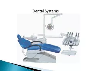
Dental Systems
Dental Systems. Dental Operating System with Headpieces Used in the restoration of teeth and treatment of gum disease The most common application is the removal of decay and filling of teeth, and the subsequent cleaning and polishing. The Major Components of the

Dental Systems
E N D
Presentation Transcript
Dental Operating System with Headpieces • Used in the restoration of teeth and treatment of gum disease • The most common application is the removal of decay and filling of teeth, and the subsequent cleaning and polishing
The Major Components of the • Dental Operating System Overview • Chair • Control (delivery) System • Handpieces • Dental Exam Light
Dental Chair • Positions the patients so the dentist can comfortably see inside the mouth • Provides comfort to the patient • It is electronically controlled and hydraulically powered • The chair is the base of the whole system and everything mounts to it • Control (delivery) system • Light
Dental Chair (Continued) • An electric motor drives the hydraulic pumps which enables the back of the chair to tilt and the base of the chair to lift • These movements are controlled by switches located on the Touchpads • Also most all models use foot controls to provide • protection from infection
Control (Delivery) System • Provides the basic utilities required for dental treatment including: • Water • Compressed air • Electricity • Vacuum
Control System • It may also include: • Handpiece controls • Foot controls • Bracket tray • Tubing flush system • Multi-syringes • Cuspidor • Suction apparatus
Water System • Water is introduced to the dental unit via the floor utility center • It has an open and close valve for the water along with a pre-regulator valve • The water system affects the operation of the 3-way syringe, cuspidor, cup filler, and handpiece water spray
Air System • Modern dental units employ an air system to run • the various air-driven dental handpieces • Because of the noise level and for safety • reasons, this system is located outside the patient • treatment area. • A large central air compressor provides the compressed air
Air System (Continued) • Most handpieces operate on air pressure in the • 20 to 80 PSI range, with a specific pressure recommended for each handpiece • Most units have a control system located on the • bracket tray where the air pressure can be adjusted
Electrical System • Provides power to indicator lights and solenoid • valves for handpieceoperation • Also provides for warm air and/or warm water • Applications • Delivery system Fiber Optic Lights • Dental Exam Lights
Vacuum System • Generally, the central vacuum system provides • suction to numerous dental units • The vacuum is connected to the dental unit with • hoses and oral evacuation equipment such as • high volume evacuation (HVE) and saliva ejectors • The dental technicians draw clean clear water • through the HVE and saliva ejector to clean any • debris after each patient • After rinsing with water, they draw air through • the system to clear all water from the hoses
Vacuum System (Continued) • The HVE is used to remove the water spray from the handpieces and multisyringe from the patient’s mouth • The saliva ejector is used when the dentist wants to keep the treatment site very dry • This suction is only good for the removal of small amounts of liquid, such as saliva
Handpieces and the Handpiece • Control System • There are three types of handpieces: • High speed handpiece (drill) • Low speed handpiece (drill) • Multi-syringe (air, water, and mist) • High and Low Speed Handpieces are powered by air driven turbines
High Speed Handpiece • Used for fine work • Body is thin and will attach directly to the handpiece hose • The turbine is located in the head of the handpiece • Needs 32 PSI of air to work correctly
Low Speed Handpiece • Used for polishing and coarse drilling • Body most often will be segmented into 3 or 4 parts • The pneumatic motor is usually a separate part • Needs 40 PSI of air to work • correctly
Multisyringe Handpiece • Delivers air, water, or an air/water mix (fine mist) • Used for rinsing, drying and blowing away debris in the oral cavity
Handpiece Control System • Automatically delivers the drive air and coolant to whichever handpiece is lifted from its holder • The control system has two main components: handpieces and foot control valve • Most handpiece controls are located on the bracket tray, the tray can usually accommodate up to three handpieces • The water flow and drive pressures are individually adjustable for each handpiece
Handpiece Control System • (Continued) • Most units use international color symbols for the identification of utilities: • A blue dot identifies a water control • A yellow dot identifies an air control • A red dot identifies the ON or activated position • Master on/off toggle • Turns on the air and water to the control system • When it is off, the items on the unit will not function
Handpiece Control System • (Continued) • Wet/Dry Toggle • Turns on the flow of coolant water to all the handpiece control blocks • Adjustment of water flow to each handpiece is made with the individual handpiece coolant water flow control knobs • Coolant Air Flow Control Knob • Adjusts the coolant air flow to all handpieces and can completely shut off the coolant air flow
Handpiece Control System • (Continued) • Drive Air Pressure Control • Adjusts the drive air pressure to each handpiece with an adjustment screw for each individual handpiece • Syringe Flow Control • Adjusts the air and water flow from the multisyringe • Generally, there are two adjustment screws to control the flow—one for air and one for water
Handpiece Control System • (Continued) • Automatic Handpiece Holder • Shuts off air and water to the handpiece when it is in its holder • When the handpiece is lifted from the holder, the valve inside the holder allows drive air and water to reach the handpiece, via the control block
Bracket Tray • Mounted on an arm • Adjustable height • Automatic Brake
Handpiece Control System • All high speed and low speed handpieces are • operated by the Dentist through the use of a foot • control valve • A valve inside the foot control regulates the • handpiece speed and provides an air signal that • activates the coolant air and water flow
Handpiece Control System • (Continued) • The wet/dry toggle allows coolant water flow to • the handpiece to be shut off without moving the • hands from the oral cavity • When activated, the chip blower removes debris • from the treatment site by sending a jet of air • through the handpiece when it is not running
Dental Exam Lights • Illuminates the patient’s mouth • It may be a ceiling track-mounted light or mounted to the dental chair • The light consists of four major assemblies: the transformer, rigid arm assembly, flex arm assembly, and the light head assembly
Dental Exam Lights (Continued) • The light is activated by the on/off switch located behind the light head assembly • The intensity switch, located on the transformer • housing, sets the light intensity to low, medium or high
Dental Exam Lights (Continued) • The flexible arm is counterbalanced to the weight of the light head and can be adjusted • If the light head moves too easily, or drifts, the spring tension in the flexible arm needs to be • Tightened • If the light head is difficult to move, the spring • tension needs to be loosened