Download
1 / 15
150 likes | 262 Views
5 Foundation Course Feeders & Antennas. EKRS Karl Davies. Twin Feeder. . Coax. Feeders. Two basic feeder types: Coax, Twin Wire. Two conductors kept at constant separation by insulation - no screen Balanced Feeder.

E N D
5 Foundation Course Feeders & Antennas EKRS Karl Davies
Twin Feeder Coax Feeders • Two basic feeder types: Coax, Twin Wire Two conductors kept at constant separation by insulation - no screen Balanced Feeder Inner Conductor is shrouded by dielectric, with outer (braided) screen. For Radio 50 Coax is used (TV is 75)
Balanced/Unbalanced • Coax is unbalanced - Inner has voltage, Outer is earthed. • Coax is widely used as its outer acts as a screen • Twin feeder is balanced - conductors have equal and opposite voltages/currents/fields. • In order to connect an unbalanced feeder to a balanced antenna (e.g. coax feeding a dipole) a transformer known as a balun is needed. • BALUN: BALanced - UNbalanced • Without a Balun rf currents flow on the outside braid, and the screening properties of coax are lost
Coax Connectors • A wide variety of connectors exist. • Common RF Connectors include BNC, PL259, N-type, SMA etc. • Ensure both the inner conductor and outer braid are assembled correctly. • Poor condition connectors are a major cause of bad SWRs etc. • Screening must be continuous through plugs and sockets. • Foundation Licence requires good understanding of two connectors - BNC, PL259.
BNC Connectors • BNC Connectors have a Bayonet locking action and are commonly used for lower power interconnections. • Take care not to mix incompatible 50 and 75 Ohm versions which have different inner pin sizes.
PL259 Connectors • Common HF/VHF connector with reasonable power handling.
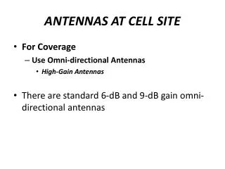
Antennas • Antennas transform AC signals into propagating radio waves. • Gain is the directing of power in the wanted direction • Need to know the following types:- • Dipole • Quarterwave ground plane • Five-eighths ground plane • Yagi • End-fed wire • Antenna size is determined by the operating wavelength, . • Example: a 2m 4 is a third of the size of a 6m/4.
Dipole • Simple - but requires a balanced feed via a balun. • Each leg is /4 long - /2 across in total.
Coax Feed Quarter Wave: /4 • Radials simulate a groundplane and are also /4 long • Sometimes called a ‘groundplane’ antenna Radials
Five-Eighths: 5/8 • 5/8 - Common antenna for mobile use • Better impedance match and gain than basic quarter wave • Radials emulate ground plane like the quarter wave
Dipole Directors Rear Reflector Gain - Circles are at -3dB, 10dB & 20dB Yagi • Dipole acts as pick up • FrontDirectors ‘focus’ to give Gain • Rear Reflector gives back/front isolation • Yagis may be horizontal or vertical
Station RF Earth End Fed Antennas • Common at HF where wavelengths are long • Needs an ATU to match it for HF multiple bands • Is unbalanced • Has strong RF voltages and currents near the house. These are likely to couple into TV and other equipment and cause EMC problems
Gain/ERP • ERP = Effective Radiated Power • ERP is the power radiated in the direction of the maximum radiation • ERP is the product of the power supplied to the antenna, multiplied by the gain of the antenna. • ERP = Power x Gain (in linear units, not dB) Units = Watts
Polarisation • Polarisation is the plane of the antennas radiating electric field. • Common polarisations are Horizontal and Vertical. • Transmitter and receiving antenna polarisations need to match for optimum signal strength. • Verticals (/4, 5/8) give vertical polarisation. • Yagis and Dipoles may be either horizontal or vertical depending on their mounting. • In complex situations polarisation can rotate.
Antenna Match - SWR • Antennas must be suited for the frequency of the transmitted signal. This is a challenge for multiband operation. • SWR - Standing Wave Ratio is a measure of the mismatch of the antenna system to the nominal impedance of the radio. • A high SWR will result in Output Power being reflected back to the Transceiver - Inefficient and Potentially Damaging. • At HF most antennas are not matched for the wide range of frequency bands, unless a matching unit is used. • SWR Meters are valuable for checking correct antenna design, installation and operation - and indicating faults • Dummy Loads permit radio tests without radiating a signal


![G9 – Antennas and Feedlines [4 exam questions - 4 groups]](https://cdn2.slideserve.com/4680362/g9-antennas-and-feedlines-4-exam-questions-4-groups-dt.jpg)