Download
1 / 29
290 likes | 536 Views
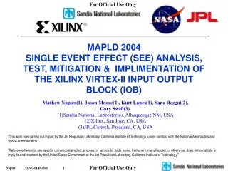
MAPLD 2004 SINGLE EVENT EFFECT (SEE) ANALYSIS, TEST, MITIGATION & IMPLIMENTATION OF THE XILINX VIRTEX-II INPUT OUTPUT BLOCK (IOB). Mathew Napier(1), Jason Moore(2), Kurt Lanes(1), Sana Rezgui(2), Gary Swift(3) (1)Sandia National Laboratories, Albuquerque NM, USA (2)Xilinx, San Jose, CA, USA

E N D
MAPLD 2004SINGLE EVENT EFFECT (SEE) ANALYSIS, TEST, MITIGATION & IMPLIMENTATION OF THE XILINX VIRTEX-II INPUT OUTPUT BLOCK (IOB) Mathew Napier(1), Jason Moore(2), Kurt Lanes(1), Sana Rezgui(2), Gary Swift(3) (1)Sandia National Laboratories, Albuquerque NM, USA (2)Xilinx, San Jose, CA, USA (3)JPL/Caltech, Pasadena, CA, USA "This work was carried out in part by the Jet Propulsion Laboratory, California Institute of Technology, under contract with the National Aeronautics and Space Administration." "Reference herein to any specific commercial product, process, or service by trade name, trademark, manufacturer, or otherwise, does not constitute or imply its endorsement by the United States Government or the Jet Propulsion Laboratory, California Institute of Technology."
Purpose & Outline • Analyze and Evaluate the different types of TMR IOB Mitigation structures. Discuss the trade offs: SEE, electrical/timing and resources, and how these trades off effect the operation and MTBF of a system. • OUTLINE • IOB • SEE IOB Mitigation • Triple Module Redundant IOB • JPL Dual-MR • SEE Trade offs • Cross Section • Signal Integrity and Timing • System Implementation • TMR, EDAC, I/O Count • High-speed Interfaces
SEU Hazards for Xilinx Technology • Configuration Memory • Configuration memory controls logic function and routing • Configuration Memory Upsets Cause • Changes logic function • Changes routing • Changes IO Configuration • Transient and Static Bit Errors • Changes data and control states • Single Event Functional Interrupt (SEFI) • Power On State Machine Upsets (POR Upset) • Causes power on reset to occur • Select Map and JTAG • Disables part configuration/scrub • Effective mitigation techniques exist for each of these error modes SRAM Configuration Memory Controls Logic Function Look-up Tables Internal Registers Store State Data SRAM Configuration Memory Controls Routing Switch Matrix
IOB Input Reg DDR mux Reg OCK1 ICK1 Reg Reg 3-State OCK2 ICK2 Reg DDR mux PAD OCK1 Reg Output OCK2 Input Output Buffer (IOB) • IOB are used to interconnect the Xilinx FPGA fabric with external devices. • Support a wide range of I/O operating standards. • Differential – LVDS… ECL • Single Ended – LVCMOS…HSTL • Silicon features greatly increasing system performance. • Flip Flops in the IOB • Double Data Rate Flip Flops • Digital Impedance control • An IOB consists of the following parts • Input path • Two DDR registers • Output path • Two DDR registers • Two 3-state DDR registers • Separate clocks for I & O • Set and reset signals are shared • Separated sync/async • Separated Set/Reset attribute per register
IOB Details 3-State Control Registers IO standard options (LVDS, etc) Output Registers Input Registers IOB Detailed View (FPGA Editor)
Xilinx Triple Module Redundancy (XTMR): Inputs • SEU Immunity requires the use of triple redundant input pins for every input signal. • Not triplicating input Globalsignals (clk, rst, etc) can seriously compromise SEU resistance. • Triplication of input data paths can be traded for EDAC. • Reduce I/O count • SEU resistance is sometimes traded-off for resource utilization. • Xilinx input Capacitance is 10pF per I/O so user needs to verify that interfacing parts can drive 30pF at speed.
XTMR : Triplicated Outputs with Minority Voters Minority Voter P • Outputs can be triplicated, using three pins for each output signal. • Minority voters monitor each of the triplicated design modules • If one module is different from the others, its output pin is driven to High-Z • Voters are triplicated TR0 P Minority Voter TR1 P Minority Voter TR2 Convergence point is outside FPGA, at trace
Minority Voter Minority Voter P P TR0 TR0 P P Minority Voter Minority Voter Z TR1 TR1 Z P P Minority Voter Minority Voter TR2 TR2 XTMR: Triplicated Output Operation - Datapath SEU • If a datapath SEU occurs, minority voter places its pin in high-Z • Remaining valid outputs drive output to correct value. • If an SEU occurs on the Minority voter, the worst it can do is disable a valid output. • To pass an incorrect output, two upsets would have to occur on the same path • Active Scrubbing of the part will eliminate the accumulation of double SEUs in Configuration Logic
Minority Voter Minority Voter P P TR0 TR0 P Minority Voter P Minority Voter TR1 TR1 TR2 TR2 Convergence point is outside FPGA, at trace XTMR : Duplicated Outputs with Minority Voters (JPL) • In this scheme (by Gary Swift at JPL), triplicated design domains are driven on to two pins • Two minority voters monitor each of the triplicated design modules • If a module is different from the others, its output pin is driven to High-Z • Voters are duplicated • If an SEU occurs on the datapath without a pin, the outputs continue operating as normal.
Minority Voter Minority Voter P P TR0 TR0 P Minority Voter P Minority Voter Z Z TR1 TR1 TR2 TR2 XTMR: Duplicated Output Operation - Datapath SEU(2) • If an SEU occurs on the datapath with a pin, that pin is driven to high-Z. • The main advantage of this technique is that it uses 2 rather than 3 pins thus reducing pin count and maintaining SEU immunity. • If an SEU occurs on the Minority voter, the worst it can do is disable a valid output. Same as XTMR
TR0 TR1 Majority Voter OBUF TR2 XTMR: Single output pin • If a design is pin-limited, you can elect not to triplicate some outputs. • A single Majority Voter can be placed in series with a single output. • This will cause additional output delay and leave the output path susceptible to SEU
XTMR Output Analysis • How many configuration bits in TMR I/O after Minority Voter? • Errors in these bits will change the IOB function and NOT be caught by the voter. • How many one bit upsets will really change the Function? • Does a Stuck at High, Stuck at Low or Inverted IOB Failure in a XTMR structure still function correctly? Can two I/O overdrive the failed one? • Voltage output High • Voltage output Low • Timing Rise/Fall • How does this change for different I/O types and switching speeds. • How to design a system that balances • SEE sensitivity • System performance and speed • Resource Utilization
Schematic Analysis • Determine the number of Configuration Memory Cells (CMC) needed to configure unprotect and TMR I/O Configuration by analyzing Xilinx schematics. • Guidelines/Assumptions • Not all SEUs will be catastrophic – therefore there are two types of SEUs (Hard and Soft Failures) • Hard Failure : 100% certainty that when it occurs – will cause a system failure • Causing the output to become inverted • Causing the output to be either stuck high/low • Changing the signaling standard to something completely different (e.g. LVCMOS to HSTL) • Causing the output to be tri-stated • Soft Failure: Uncertain as to the effect • Changing the signaling standard to something similar (LVCMOS to LVTTL) • Changing the drive strength or slew rate • Changing the termination
Schematic Analysis Results • Schematic Analysis of this path = 109 bits (but only 92 “essential) • 26 Hard Failures • 66 Soft Failures CLB LUT Routing to IOB IOB
TMR Output Results • Schematic Analysis of this configuration = 173 bits • 27 Hard Failures • 122 Soft Failures • TMR has larger cross section then unprotected . AC analysis will determine which type is more robust. CLB and Routing IOB
SEE Mitigated IOB Signal Integrity and Timing • MEMEC Insight MB-2000 board used as test platform to test Electrical and Timing Characteristics of XTMR. • Tied Three I/O together and ran through four different cases: • Normal, Stuck at High, Stuck at Low, Inverted • For Each Case the following measurements were measured. • Voh, Vol, Tr, Tf • 4GHz Scope Pictures • I/O Types Evaluated included • 1.8V/2.5V/3.3V LVCMOS & LVTTL, LVDCI (Impedance control) & LVDS. • Fast and Slow Slew Rate. • Hyperlinx Simulations were preformed on all of the above cases to verify correlation between measured and simulated data. • JPLs dual-redundant minority voters mitigation scheme will fail all of the above operating conditions if one of the I/Os fail.
SEE Mitigated IOB Signal Integrity and Timing • XTMR 1.8V LVCMOS • One output Inverted • Voh downto 1.4V down from 1.8V • Vol upto .4V up from 0V • Noise do to lack of termination Normal Inverted
SEE Mitigated IOB Signal Integrity and Timing Stuck at High • LVCMOS1.8V • Measured • Voh = 1.72V • Vol = .4V • Tr = .58ns • Tf = .51ns • Simulated • Voh = 1.79V • Vol = .54V • Tr = .80ns • Tf = .60ns Hyperlynx IBIS Model Stuck at High Simulation Stuck at Low • Simulated • Voh = 1.26V • Vol = -.06V • Tr = .60ns • Tf = .70ns • LVCMOS1.8V • Measured • Voh = 1.44V • Vol = -.04V • Tr = .62ns • Tf = .52ns Simulation data correlates with measured data Stuck at Low Simulation
SEE Mitigated IOB Signal Integrity and Timing • Measured Data Spread Sheet Normal Stuck At Low Stuck At Low INV SAH Failure limits V output low margin or violates level
CMC Failure Comparison • How does Naked I/O compare to TMR in dynamic test in the beam and Fault Injection? • Test will show CMC sensitivity do to switching failures large enough to break output switching state. • TMR displayed zero failures at 3.3V and 1.8V • Naked I/O has much larger CMC failure cross section then TMR setup. • I/O test design is only running at 30MHz. TMR failures may show up at higher speeds. Inverted
System Goals & Implimentation • GOALS • Xilinx FPGA technology is a Mission Enabling Technology • SEU Goal – Develop a design that produces the SEU performance comparable to that of a fully hardened design while exploiting the capabilities of state-of-the-art CMOS process technologies • SEU Result – System Upset rate is superior to that which could be achieved with unmitigated SEU hard logic • IMPLIMENTATION • Command and control logic is implemented in SEU hard logic • Processor Memory includes Parity protection • Fail over to boot code • SEU detection and recovery for SEU soft devices is automatic and occurs without ground intervention • SEU induced outages that do not require ground intervention are booked against mission availability • Although not a specific requirement good SEU performance under nominal solar flare conditions is desired
SEU Mitigation and Error Control • Mitigate IO Upsets • TMR of IO for clocks and address signals • EDAC for data path signals • Mitigate Configuration Memory Upsets • TMR internal logic • Configuration memory scrubbing to prevent error accumulation • Design approach does not include POR upset mitigation • Use of shadow devices effective against POR errors • POR Error rate is very low • The flight system makes extensive use of several techniques to exploit the advantages of nano-meter CMOS technology while maintaining excellent SEU performance • Multiple bit Reed-Solomon forward error correction codes • Single bit error correcting codes • Simple parity error detection • Cyclic-Redundancy-Check for burst error correction • Triple Modular Redundancy • Error Scrubbing • Mitigation technique is selected based upon error rate, vulnerability, system impact, and implementation complexity • Mitigation techniques provide coverage for dynamic SEU errors Error Correction Techniques Implemented for SEU Mitigation Improve the Overall Design Robustness and Reliability
Mitigation Overview – Sensor Data Processor (SDP) • Processes 8Gbps of Data. • Outputs 340Mbits of Processed Data. • Architecture • Fiber Receiver and SERDES link, 4 channels at a maximum of 160Mpix ea. • Four Quadrant Processors for data processing. Contains 640 Mbytes of SDRAM for data storage • 320 bit 85Mhz SDRAM 1.8V • Can generate upto 340Mbits/s of Source Packet Data • One Central Virtex For Data Networking • De-mux data from Serdes chips outputs to 4 processing channels/Quadrant Xilinx • Controls Frame Summation Rates and Reference Frame Generation Rates. • Transfer Source Packets to downlink modules at up to 340Mbits/s Max • USES Compresses source Packets.
XC2V3000 XC2V3000 640MB +ECC 640MB +ECC 640MB +ECC 640MB +ECC Temp. Voltage Gilgamesh XC2V3000 XC2V3000 A-I2C CTM Mitigation Overview – Sensor Data Processor (SDP) RS-ECC RS-ECC TMR TMR Fiber Input 320 ECC ECC 320 PIX/Packet SERDES Osc JTAG JTAG PIX/Packet I2C I2C ECC/CRC TMR XC2V3000 Interface Control TMR TMR PIX/Packet PIX/Packet 320 JTAG 320 ECC/TMR I2C TIME System CLK Packets JTAG JTAG I2C I2C To DLM/DLC PXS SDP CTM
SDP- SDRAM • SDRAM interface, 1 per Quadrant Virtex • 20 1.8V Micron Mobile SDRAM • 1.8V LVTTL I/O • 320 Bit Data Bus – 240 Pixel DATA, 80 ECC • Data is Reed Solomon Encoded • TMR'd outputs from Virtex: address,control and Clock • Address and control signals are AC Terminated. • TMR’d input to Virtex: Clock Feedback – Used to de-skew the SDRAM Clock • Currently running at 85MHz designed to operate at 100MHz • Test • Measured TMR SDRAM Addr, RAS and CAS signals for the following cases. • Inverted, Stuck High, Stuck Low • Measured Voh, Vol, Tr and Tf. • Count the Number of Reed Solomon Errors, If any. SDRAM ADDRESS & CONTROL
SDP- SDRAM(2) SDRAM Address Normal SDRAM Address One I/O Inverted
SDP- SDRAM(3) No SDRAM Errors for All Three Failure Cases
Lessons Learned • Triple redundant outputs for >2.5V LVCMOS or LVTLL achieve correct Vol and Voh levels for all failure cases • For low voltage I/O <1.8V Thresholds are very close to margins for failure conditions and may violate other parts spec. • For SDRAM interface 1.8V I/O tolerated all three failure cases at room temperature. • Double redundant outputs will not meet the correct Vol and Voh levels under I/O failure. • Rise and/or Fall times are lengthened do to I/O failure. May cause more failures at higher speeds. • Recommendation • If resources permit XTMR output for all control signals is recommended regardless of I/O type. • High Speed, Jitter or Duty Cycle Sensitive Devices Outputs need special consideration • EDAC on Data busses are ideal for IOB failure protection.