Download
1 / 14
140 likes | 408 Views
Asper School of Business University of Manitoba. Systems Analysis & Design. Instructor: Bob Travica. Analyzing system processes: Use Case Diagram Updated 2013. Outline. The use case concept Business events and systems Elements of use case diagram

E N D
Asper School of Business University of Manitoba Systems Analysis & Design Instructor: Bob Travica Analyzing system processes:Use Case DiagramUpdated 2013
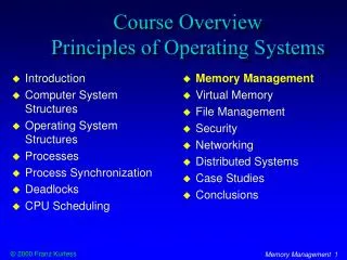
Outline • The use case concept • Business events and systems • Elements of use case diagram • Include and Extend relationships between use cases • Reading use case diagrams • Creating use case diagrams 3510 Systems Analysis & Design * Bob Travica
Figure 6-3 Use case concept • Use case is a model of system functionality. • Think of main functions a system performs for users – “cases” of using a system. Use case Use Case Diagram of Order-Entry Subsystem for RMO
Use case diagram in system documentation • Use Case helps to model system requirements • Easy for users to understand 3510 Systems Analysis & Design * Bob Travica
Business Event concept • A stimulus that requires a system’s response • Delineated in time; stands on its own Figure 5-2 Events affecting a Charge Account Processing System that determine what system has to do – functions, use cases
Event types • External Events (outside an IS) • Caused by external agent (human, system) • Temporal Events (inside an IS) • Occur at a certain point in calendar time • State Events (inside an IS) • Changes in system states, such as data (QuantityOnHand=<ReorderAmount inventory quantity reduction) 3510 Systems Analysis & Design * Bob Travica
Figure 5-10 Events Table Input Output 3510 Systems Analysis & Design * Bob Travica
Elements of use case diagram:Actor • Actor is someone interacting with use case (system function). Named by noun. • Similar to the concept of user, but a user can play different roles; (example: a prof. can be instructor and researcher – plays 2 roles with two systems). Name • Actor triggers (initiates, starts) use case (a system function). • Actor has responsibility toward the system (inputs), and Actor have expectations from the system (outputs). 3510 Systems Analysis & Design * Bob Travica
= Use Case Elements of use case diagram:Use Case • System function (process – automated or manual). Named by verb. Do something • Each Actor must be linked to a use case, while some use cases may not be linked to actors. 3510 Systems Analysis & Design * Bob Travica
Connection between Actor and Use Case Boundary of system Include relationship between Use Cases (one UC must call another; e.g., Login UC includes User Authentication UC) <<include>> <<extend>> Extend relationship between Use Cases (one UC calls Another under certain condition; think of if-then decision points) Elements of use case diagram:Other details 3510 Systems Analysis & Design * Bob Travica
Include relationship • Include relationship – a standard case linked to a mandatory use case. • Example: to Authorize Car Loan (standard use case), a clerk must run Check Client’s Credit History (include use case). • The standard UC includesthe mandatory UC (use the verb to figure direction arrow). • Standard use case can NOT execute without the include case tight coupling. • Note: Visio calls this “uses” relationship. 3510 Systems Analysis & Design * Bob Travica
Reading use case diagramwith Include relationship 3510 Systems Analysis & Design * Bob Travica
Extend relationship • Extend relationship – linking an optional use case to a standard use case. • Example: Register Course (standard use case) may have Register for Special Class (extend use case) – class for non-standard students, in unusual time, with special topics, requiring extra fees…). • The optional UC extends the standard UC • Standard use case can execute without the extend case loose coupling. Reading extend relationship 3510 Systems Analysis & Design * Bob Travica
How to create use case diagram 1. List main system functions (use cases) in a column: • think of business events demanding system’s response • users’ goals/needs to be accomplished via the system • Create, Read, Update, Delete (CRUD) data tasks • Naming use cases – user’s needs usually can be translated in data tasks 2. Draw ovals around the function labels 3. Draw system boundary 4. Draw actors and connect them with use cases (if more intuitive, this can be done as step 2) 5. Specify include and extend relationships between use cases (yes, at the end - not before, as this may pull you into process thinking, which does not apply in UC diagramming). 3510 Systems Analysis & Design * Bob Travica