Download
1 / 15
150 likes | 318 Views
Feeds and LNA’s for SKA TDP Progress Report, June 4, 2010 S. Weinreb Caltech. Caltech EE group SKA-Mid receiver requirements Five candidate feeds Quadridge update ATA feed update Eleven update QSC update (by G. Cortes). Caltech EE Radio Astronomy Group, May, 2010.

E N D
Feeds and LNA’s for SKA TDP Progress Report, June 4, 2010 S. Weinreb Caltech Caltech EE group SKA-Mid receiver requirements Five candidate feeds Quadridge update ATA feed update Eleven update QSC update (by G. Cortes)
Caltech EE Radio Astronomy Group, May, 2010 Ahmed Akgiray – Ph.D. student SKA feed design and integration Damon Russell – Ph.D. student LNA design and testing Hamdi Mani – Research technician worked on everything Steve Smith – Research engineer, LNA’s, systems Hector Navarette – Research technician, LNA’s construction Glenn Jones - Ph.D. graduate 2009 works on wide bandwidth processing Joe Bardin – Ph.D. graduate SiGe Cryogenic LNA’s Zan Zhang – MSEE graduate 2010 SKA feed design and tests
SKA Mid Reflector Array – Receiver Requirements 1. Operation from 0.3 to 10 GHz A. > 60 % Efficiency B. Tsys < 35K for 0.8 to 10 GHz 2. Secondary but important considerations A. Power consumption B. Manufacturabililty C. Maintainability D. Cost including IP rights E. Stabiliy for dynamic range and polarization 3. Reference design A. Uncooled 0.3 to 1.4 GHz receiver with 0.8m diameter B. Cooled 1.4 to 10 GHz receiver with 0.3m diameter dewar C. Benchmark against octave band receiver (0.7 to 1.4 or 5 to 10 GHz)
Status of Candidate Feeds QUADRIDGE – Cooled 3.5 to 14 GHz on 34m telescope with measured efficiency and Tsys. Versions for 0.3 to 1.5 and1.4 to 10 GHz in design. ATA – Uncooled 0.5 to 11 GHz on 42 ATA antennas with 40 to 100K Tsys. Prototypes of cooled 1 to 10 GHz versions are under test. QSC - Uncooled 0.4 to 4 GHz prototype constructed and tested showing good patterns and return loss. Update by G. Cortes follows. ELEVEN – Cooled 2 to 12 GHz prototype with measured patterns, return loss and noise. A 1 to 10 GHz cooled prototype under construction and will be delivered to Caltech this summer. SINUOUS – In design and test at NRAO. Uses foam support and dewar.
Improvements to Quadridge Feed Good return loss is achieved from 1.4 – 11GHz
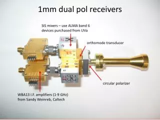
Concept for Integration of LNA’s Into Dual-Polarized Quad-Ridge Feed • Single-ended 100 ohm LNA’s are mounted on bottom side of fins with probe coupling across slot to opposite fin. • Coaxial output and bias lines of LNA will be routed along back of fin • LNA will be on a bolt-in copper carrier for easy replacment Probe coupling 100 ohm slot line to microstrip; LNA 5mm LNA on 10mm base could be repackaged to 5mm x 20mm area LNA
Photograph of 0.5 to 14 GHz System at Goldstone DSS28, October, 2008 Secondary(shadow) 2-14 GHz Cooled Feed 0.5-4 GHzFeed, Cooled LNA Rotatable Tertiary
Efficiency and Tsys of Quadrige Feed Measured on 34m GAVRT Telescope
Two Concepts for Cooling of the ATA Feed • Current ATA feed is uncooled (with LNA cooled to 65K) and covers 0.5 to 11 GHz with system noise temperature of 40 to 100K • Two concepts to cool the feed to reduce Tsys to < 35K over the band of 1 to 10 GHz or higher are being investigated. Cooled feed in aluminum vacuum chamber with Mylar window Cooled feed in glass bulb vacuum chamber
Coolable Prototype of ATA Feed at Caltech for Tests of Impedance, Pattern, and Noise Temperature • Feed made of copper (to be plated) and is ~40 cm long • Feed tips are connected to LNA within pyramid by 93 ohm coaxial cable as shown at right below. • Tests will be conducted during summer of 2010
Eleven Feed - Noise of Cryogenic Feed and LNA Now Measured • (Beaudoin, Klein, Yang, Kildal, and others) • Noise measured for feed, baluns, and LNA’s at 20K • Measured patterns predict good efficiency
Very Low Noise Amplifier Development Summary - 2009 • InP HEMTS - Indium-phosphide high-electron-mobility transistors have been implemented in almost all low-noise amplifiers in radio astronomy for the past 10 years with little change in performance. They are usually cooled to 15K to reduce the noise by an order of magnitude. The noise performance from wafer to wafer can vary by a factor of two due to unknown reasons. • Room Temperature Very Low Noise Amplifiers. - The cost of the large number of receivers required by arrays could be greatly reduced if LNA’S with sufficiently low noise could be realized at room temperature. Transistor device improvements may enable this. Current performance is around 17K noise or 0.25 dB noise figure at 1.4 GHz; a goal is < 10K of noise (0.14 dB NF) at 1.4 GHz. • SiGe HBT - A promising new transistor, the SiGe HBT, is being rapidly developed for high speed computer and communication applications. These transistors greatly improve in current gain and transconductance when cooled. During the past year SiGe amplifiers with noise temperatures of <5K at frequencies under 4 GHz have been built and tested at Caltech using transistors from IBM and STM. Advantages are: 1) simultaneous noise and power match by feedback, 2) high gain stability, 3) can be integrated with CMOS on the same chip. 4) rapidly developing technology.
Caltech-Developed Cryogenic LNA’s Caltech EE has Delivered 400 LNA’s to Other Research Centers During the Past 6 Years e 6 Models, @ 15K SiGe HBT 001 to 1 GHz < 6K 1 to 3 GHz < 8K InP HEMT 0.5 to 11 GHz, Tn < 6K 4 to 14 GHz, Tn < 8K 6 to 20 GHz, Tn < 12K 11 to 26 GHz, Tn < 20K Differential InP HEMT 0.5 to 11 GHz,Tn <18K at 60K S. Weinreb
Packaged Differential Cryogenic LNA Will be used for tests of ATA, QSC, and Eleven feeds and is available if a differential transition to a quadridge feed is desired. Optimum generator impedance is in the 200 ohm range. InP HEMT MMIC LNA 200 ohm differential input 50 ohm coaxial output
Noise Temperature Measurement of Differential LNA’s • Noise temperature of a differential amplifier can be measured with the Y factor method by dipping a termination resistor in LN2 at 77K • The resistance change vs temperature can be measured very accurately at DC with on ohmmeter. The change in typical thin-film resistance is negligible. • Shown below is a small board with two 270 ohm resistors connected to two differential LNA’s with a gold-plated SS tubing quad transmission lines. S. Weinreb, Jun 2009