Download

1 / 58
600 likes | 749 Views
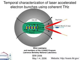
Single-Shot Measurement of Femtosecond Electron Bunches at SLAC. Adrian L Cavalieri, David M Fritz, SooHeyong Lee, Philip H Bucksbaum, David A Reis (FOCUS Center, University of Michigan) Holger Schlarb ( DESY ) Patrick Krejcik, Jerome Hastings ( SLAC/SSRL ).

E N D
Single-Shot Measurement of Femtosecond Electron Bunches at SLAC Adrian L Cavalieri, David M Fritz, SooHeyong Lee, Philip H Bucksbaum, David A Reis (FOCUS Center, University of Michigan) Holger Schlarb (DESY) Patrick Krejcik, Jerome Hastings (SLAC/SSRL)
Next Generation Light Sources:From a Machine Standpoint • To reach threshold for SASE longitudinal extent of the accelerated bunches must be controlled • Bunch length information, on a shot-to-shot basis will be a critical parameter by which operators tune new machines. • Operators may also want to know charge distribution within individual bunches. • Electro-Optic Sampling is a technique that can deliver this information.
Next Generation Light Sources:From a User Standpoint • Unprecedented levels of peak brightness and photons/pulse will open the doors to experimentalists studying: • multi-photon x-ray processes • weakly scattering biological systems • Pulse duration over which the x-ray photons are delivered dictates ultimate resolution with which time-dependent processes can be studied • To take full advantage of the temporal resolution that sources can provide, users will need: • Duration of each bunch that produces an incident x-ray pulse • Accurate arrival time of each x-ray pulse on target with respect to an external excitation (to perform “pump-probe” experiments) • Electro-Optic Sampling is a technique that can deliver this information
User Constraints • EOS measurements are made with ultra-fast probe pulses from a laser oscillator – time is measured with respect to ticks of this oscillator • In order for this information to be pertinent to pump-probe experiments, the same oscillator that produces the probe pulses must also be used to pump the experiment • Therefore, the laser oscillator must be located near the experiment hutch, which is in general, far from the EO chamber • A path length stabilized transport system must be designed to deliver the probe pulse to the experiment without dispersion. • User constraints are not trivial to meet, but, they set this measurement apart from other techniques
SPPS at SLAC • R&D facility for LCLS (Linac Coherent Light Source) • Beam Delivered to SPPS: • 30GeV electron bunches • 21 billion electrons – 3.4nC of charge • Compressed bunch length of 12microns RMS • 80fs FWHM x-ray pulse duration • Of interest to experimentalists since it is the highest peak spectral brilliance x-ray source in the world • Currently we are collecting bunch duration and jitter data
Accelerator Laser Room FFTB The SPPS Facility: R&D for XFEL’s
Global Timing • Assume stable laser pulse repetition rate on us timescale • Time between pulses is constant and known (9.8ns; 102MHz) • Once path difference between EO chamber and experiment is determined, timing information learned at EO chamber can be mapped to the experiment • Laser Oscillator becomes master clock
Electro-Optic Effect • Mixing of a DC or slowly varying E-field with a so-called “time-varying” optical E-field in a crystal • Effect of slowly varying field on the crystal is measured with laser probe • Such a measurement yields temporal profile of the perturbing field • First used to measure transient signals on transmission lines in 1982 • First used to measure transient fields in free space in 1995 • This measurement relies on the fact that a single pulse is used to generate the transient and probe the resultant field • Using time delays the shape of the transient can be swept out in time • At the SPPS and accelerator facilities in general this will not be possible (no inherent synchronization)
Spatially Resolved EOS • Scanning EOS vs. single-shot EOS • Features on ~100fs timescale reproduced • Departure from measurement at SLAC/SPPS • Intrinsically synchronized • Table-top measurement – (access to setup) • Previous bunch measurements using EO effect had been spectrally resolved J. Shan et. al., Opt. Lett. 25, 426 (2000)
Spatially Resolved Electro-Optic Sampling (EOS) Laser probe early relative to electron bunch Laser probe later relative to electron bunch EO Crystal
Spatially Resolved EOS (long bunch) EO Crystal
Spatially Resolved EOS Integrating detector; iCCD polarizing beamsplitter time; space Temporal information is encoded on transverse profile of laser beam
iCCD readout Recorded Data data collapsed on time axis integrated intensity integrated intensity time time
EO Capability:Single-Shot Electron Bunch Length Data • Direct relationship between width of signal and length of electron bunch • Feature size is actually broader than the associated electron bunch due to: • Sampling crystal thickness • Laser probe pulse duration • Detector Optics
EO Capability: Shot-to-Shot Jitter • Position of EO signal jumps from frame to frame, or column to column. • Jumps correspond to different arrival time of bunch w.r.t. the laser probe pulse • With this data and minimal effort we can extract • Jitter of the SLAC machine w.r.t. the reference RF • Arrival time of the x-ray pulse at experiment w.r.t. the pump that drives the time-dependent process being studied
EO Capability: Long Term Drift • This data set demonstrates long term drift between sources • Feedback is used to maintain the synchronization • Tracking changes made in optical pathlength of the transport system keeps timing information valid
Electro-Optic Effect • Cross-section of index-ellipsoid, perpendicular to direction of probe propagation • Index ellipsoid is modified by an applied DC electric field • Modified principle axes of crystal system are obtained • Index of refraction for radiation polarized along these axes is obtained • Probe laser field is decomposed in primed coordinate system • Phase shift between components is obtained
Time-Dependent EO Effect • Best known example of a time-dependent EO effect is a Pockels cell • Optical device used for “pulse picking” • Length of nonlinear crystal and applied voltage chosen for half wave phase shift • Incident linearly polarized exits the cell in the orthogonal linear polarization state • Our sampling uses ZnTe crystal which has a Pockels, or 1st Order, EO effect • Interaction length is not fixed • Applied voltage is not fixed • We are mostly concerned with the time at which the effect turns on, and when it turns off • Shape of the effect will reveal bunch charge distribution
Transverse Electric Field of 30GeV Electron Bunch Distinct Treatment for Extreme Cases: assume: Steady-state reached (use Gauss’s Law) Coeff. for Gaussian charge distribution
Transverse Electric Field of 30GeV Electron Bunch • Approximate field assuming: • Steady-state • Fields are actually much more complicated due to: • Apertures upstream • Impedance mismatch • Resistance in beampipe • Accurate calculation requires numerical analysis • Our crystal is in a 6” 6-way vacuum cross so this approximation turns out to be very good
Effect of Long Pulse Probe Laser • Probe pulse longer than e-bunch • EO signal will be broadened • If probe pulse shape is very well known, we should be able to deconvolve e-bunch shape • Signal to background problems introduced • Probe pulse uncompressed (~10’s of picoseconds or longer) • Measurement will yield no spatially dependent signal
Ultrafast Laser Transport • Laser Oscillator that generates probe pulses is located 150m from the EO setup • Probe pulses are transported through single mode polarization preserving optical fiber • Probe pulse duration limits resolution of bunch duration and jitter measurement • Dispersion in fiber optic results in temporal broadening of the broadband (20nm) optical pulse • Estimated transmitted pulse duration ~1ns • Dispersion compensation is incorporated into the transport system • Grating Pair to compensate for GVD in fiber • Pulse Shaper for higher order dispersion contributed by fiber, grating stretcher, and other optical components
SLM640-pixel Ultrafast Laser Transport: Pulse Shaper • Pulse Shaper consists of a 640-pixel SLM in Fourier Plane of a 4f zero dispersion stretcher • Can compensate for arbitrary dispersion, but amount of compensation is limited • Genetic Algorithm (GA) is used to find the configuration of the SLM that minimizes total transport system dispersion • frequency doubling of throughput used as feedback • in conjunction with grating pair, nearly transform limited pulses can be recovered at EO chamber
Ultrafast Laser Transport: 3rd Order Correction • Data taken with a 110m spool of test fiber at UofM with 128-pixel SLM • Spectral width of transmitted pulse is ~10nm Without Pulse Shaper With Pulse Shaper FWHM 600fs FWHM 160fs
135fs (FWHM) Ultrafast Laser Transport: autocorrelation in FFTB • Autocorrelator used as diagnostic • transport system is sensitive • remote operation possible • Direct verification of short laser pulse arriving at the EO chamber • Find pulse is not transform limited • Improvement can be made in GA • Improvement can be made in chromatic aberration in pulse shaper • Fixed phase mask can be used to increase capacity of pulse shaper Schematic PMT BBO
Overlap in EO Crystal • Problem: Overlap 30um laser probe, with 30um e-bunch, in 30um thick crystal • Phase lock two sources to one another • 28th harmonic of laser oscillator with accelerator frequency • “Bucket jump” for coarse timing • Use photodiode and oscilloscope as feedback • Scan optical delay line for fine timing • Use EO signal as feedback • Perfect synchronization not possible due to jitter of electron beam and laser pulse repetition rate w.r.t. reference RF
Laser Pulse e-Bunch Synchronization • Accelerator electronics are synchronized to 476MHz reference • The RF accelerating frequency is 2856MHz • Electron Bunches will arrive in phase with accelerating frequency • Electronic Triggers indicate the arrival time of the bunch with ~ns precision • The Ti:sapphire oscillator that generates probe pulses is synchronized to the RF accelerating frequency • The repetition rate of the Ti:sapphire oscillator is 102MHz, the 28th sub-harmonic of the accelerator frequency • The repetition rate is actively stabilized by making slight adjustments to the cavity length
Phase Lock: Active Stabilization • 2856MHz reference and 28th harmonic of laser oscillator output are mixed • Mixed output is filtered and amplified to drive a piezo electric crystal • End mirror of oscillator cavity is mounted on the piezo electric crystal • Phase lock good to sub-100fs level (with clean reference) LO IF Ti:sapphire Oscillator 2856MHz Reference RF 2856MHz Band Pass
Oscillator Output Locked to Reference RF (bucket spacing ) Phase Locked Oscillator Output 476MHz Backbone Accelerator Frequency 2856MHz Reference RF Generated from Backbone Frequency
Coarse Timing • Overlap of the e-bunch and the probe pulse is performed in two steps: • The first step consists of bucket jumps • Use photodiode and scope for feedback
Timing: Fine Adjustment • Overlap of the e-bunch and the probe pulse is performed in two steps: • The second step requires adjusting an optical time delay by • Uses EO signal for feedback
EO Crystal Geometry EO Chamber In Crystal Plane [100] projection of laser beam [1-10] e-beam into board
First EO Signal (12 December 2003) • Integrated photodiode signal observed on 400MHz digital oscilloscope • No spatially dependent information, searches for overall changes in signal strength in one of the polarization components of the probe • minimized single-shot window to increase interaction region and maximize overall modulation
First spatially resolved signal(7 December 2003) • First spatially resolved EO signal • Main bunch evident as well as subsequent THz reflections • Captured with intensified CCD (LaVision, borrowed from DESY) • iCCD gating superior to any other proposed technique • iCCD Necessary for singleshot EOS measurement (signal to background issue) S-polarized single-shot window P-polarized global time delay (mm)
First clear time-dependent signal(21 December 2003) • Single-shot time scan taken with Andor iStar • Input beam parameters “tweaked” to show clear EO signal • Divergence of input beam changed • Single-shot window expanded • Multiple stripes are a source of concern • Not clear that intensity goes up in one polarization and down in the other • Too large in time to be real • Over-rotation? • Reflection? circular polarization; raw data single-shot window global delay (mm)
Single-shot time scan(30 January 2004) • Treat the ZnTe crystal as a virtual source • 100fs bunch would be encoded onto 30um of the laser polarization profile • Use singlet to image crystal • Multiple strip pattern, caused by diffraction vanishes • Intensity in one polarization clearly increases, while decreasing in the orthogonal polarization • Conservation is good. circular polarization; raw data single-shot window global delay (mm)
Effect of accelerator parameters on EO signal:Observation of resolution limit • ZnTe crystal remounted closer to electron beam • Larger EO signal observed • EO signal studied as a function of the 2-6 klystron phase • Changing energy spread in bunch changes compression • Single-shot EO feature size clearly bottoms out at 1ps – as expected, due to crystal thickness • In region above resolution limit, pulse duration agrees with numerical simulation (14 February 2004)
At time the probe and e-bunch field interact in region At time the probe and e-bunch field interact in region This process continues until the e-bunch has propagated past the crystal The projected area swept out on the detector after the analyzer no longer represents the bunch duration or time of arrival accurately The signal has been smeared Resolution Limitations: Thick Crystal Smear
Resolution Limitations: Index Mismatch Direction of Propagation • Index mismatch between THz pulse and Probe Pulse = .6 • Corresponding to 400fs walk-off in 200microns of crystal • THz pulse reaches the exit face 400fs before the optical probe • Interaction Region will always be limited by the walk-off • A thick crystal will always ruin the jitter measurement • Cannot be sure of where the interaction occurred in the crystal Interaction Region
Estimate Frequency Response Cut-Off EO crystal sign of effect accumulated effect
Effect of accelerator parameters on EO signal:Observation of resolution limit • Phase ramp scan taken with 200um crystal • 200um crystal is .5mm from e-beam (1mm crystal had been 1cm from beam) • Based on simple estimate, expect cut-off frequency for 200um crystal to be 5 times higher than for 1mm crystal • Expect 5 times more resolution with 200um crystal • Resolution limit not as obvious in this scan • Appears that resolution limit is no longer dominated by crystal thickness
200um ZnTe Phase Ramp Scan • Estimate of EO signal FWHM indicate a resolution limit is again being reached • FWHM bottoms out, but signal height continues to rise as ramp moves toward optimum compression • Resolution limit due to combination of factors • Crystal is too thick • Imaging is not adequate to resolve virtual source features at EO crystal
200um ZnTe Single-Shot Data • Typical on crest single-shot data • FWHM ~300fs • Estimate of pixel-to-time conversion made with slope of time scan data • Conversion factor is ~20fs/pixel • Resolution can be increased by increasing the magnification of our imaging system • Feature resembles a sum of two gaussians • Pedestal is much larger than expected ~300fs FWHM
Fun with the Instrument Function K. Gaffney time (fs) Is the measurement plausible? • GOAL: Guess an instrument function and bunch shape that return a convolution that looks like the single-shot data • Red line: • sum of two gaussians, one with sigma = 80fs, the other 20% amplitude, sigma = 1ps • Instrument function estimated to be gaussian with sigma = 200fs • combine laser pusle duration with imaging imperfections • The blue line is the convolution of the two
Is the measurement plausible? • There is good agreement between our test functions and the actual experimental data • Instrument function – purely a guess, but seems reasonable • We should be able to do better than guess with the e-bunch charge distribution function, since the compressor has been simulated Single-shot data w/ convolution function
Simulated Longitudinal Bunch Charge Distribution • Simulation shows wings in the bunch out to 1ps, but amplitude of ~1% • To match our data need much more significant wings • Width of the instrument function is fixed by the width of the central feature • Wings could be enhanced since our crystal is thick • Interaction region for sharp features is limited by walkoff • Interaction region for slow features not affected by walk-off
Effect of Poor Imaging on Single-Shot Data poor imaging • Broadening also due to insufficient resolution in imaging system • 100fs feature corresponds to a 30um feature in the beam • Current chamber limits achievable resolution • Broadening is still due predominantly to crystal thickness and cut-off frequency reference