Download
1 / 18
180 likes | 311 Views
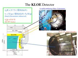
Mar. 03, ‘05. Detector magnet and Structure for the GLD Detector. KEK Hiroshi Yamaoka. Iron Yoke. Solenoid. Cable. Muon Tracker. Self-weight. H-Cal. EM Cal. Main Tracker. Uniformity. VTX. B. Mag. force. Earthquake. Introduction. Yoke design ・ Design against magnetic field

E N D
Mar. 03, ‘05 Detector magnet and Structure for the GLD Detector KEK Hiroshi Yamaoka
Iron Yoke Solenoid Cable Muon Tracker Self-weight H-Cal EM Cal Main Tracker Uniformity VTX B Mag. force Earthquake Introduction Yoke design ・Design against magnetic field Optimize plate thickness/length to be satisfied field uniformity. Check leakage field ・Design against forces Self-weight, Earthquake, Magnetic force ・Assembly with keeping good accuracy ・Minimize support structure ・Cable space, support structure for sub-detectors ・Easy access to sub-detectors ・Cost reduction
Boundary conditions for yoke design Belle Magnetic Field Bc= 3 Tesla Material: S10C(JIS) Carbon= 0.1wt% st=310MPa se=205MPa sallow=120MPa Field Uniformity <2mm, <20mm Permeability Air gap for muon is 10cm. These dimensions are fixed, Coil length, yoke dimensions are changed.
Z1 Z2 Solenoid magnet R2 R1 3T Magnetic Field Calculation ANSYS:Two-dimensional Static Magnetic Analysis Infinite elements Axisymmetric Air Iron ・Plenty of amount of iron ・Minimize Z1,R1 ・Optimize Z2,R2 Coil Input; Permeability Current density(Coil) *Material properties Main Tracker Perform ANSYS calculation to optimize Iron Yoke configuration.
Calculations Coil-L dz 4.25m
Unif.=18mm *Air gap=10cm 2mm R2.05m R1.8m 1 R1.0m R0.4m 0 8 layers Iron 7 layers
Fringe/Leakage field Magnetic field/ Flux line
Air gap=5cm, Uniformity=20mm Magnetic field/ Flux line Unit: Tesla Coil=L4.58m 7.4m Air gap=1cm, Uniformity=20mm Magnetic field/ Flux line Unit: Tesla Coil=L4.50m 7.16m
Max. 90MPa<120MPa Max. 1.8mm Stress/deformation of End Yoke Fixed 18000tons Symmetry is NOT defined! = 18400tons ANSYS: 18342tons
Stress/deformation of Barrel Yoke Max. 7mm Thickness= 5cm Max. 65MPa<120MPa 13300tons Fixed Fixed
4.3mm 30mm 4.2mm Superconducting Solenoid Superconductor * Uniformity=2mm, Air gap=10cm (For ATLAS) NbTi:Cu:Al= 1:0.9:15.6 Strand diameter: 1.23mm Filament diameter: 20mm Jc in NbTi at 5T, 4.2K: > 2750A/mm2 Ic at 5T, 4.2K: > 20300A
Support cylinder (t=50mm) Deformation of the coil Conductor (h=30mm) Solenoid center 8mm 4mm R4.0m 4.93m(Half) Stress level in the coil Development of High-strength Al Circum. direction Axial direction Compression By Makida
Cryostat design Model-1 2000tons Load conditions Weight of the calorimeter: 2000tons Weight of the solenoid : ~140tons Vacuum : 0.1MPa Fixed Fixed Model-2 Thickness of ・Inner vacuum vessel ・End plates were optimized. SUS304 st =530MPa sy =210MPa sallow=140MPa • Outer vac. vessel • 40mm Fixed Fixed p: Buckling pressure 0.1MPa x 2(safety factor) 2000tons
t=40mm t=60mm t=100mm 274MPa>140MPa 15mm 2000tons Fixed Fixed 2000tons x0.3G 125MPa Fixed Fixed 2000tons Fixed Fixed 9mm Model-1 Material: SUS304 Model-2 t=40mm(Outer) t=60mm(Inner) t=100mm (End plate) 118MPa<140MPa Stiffness: D 9mm E: Young’s modulus I: Moment of Inertia Important Weight of the calorimater should be supported at horizontal position. - Calorimeter is divided to several modules in the axial direction. - One module of calorimeter has to be stiff enough.
Iron Yoke Moun EM-Cal Solenoid H-Cal Main track Solenoid Magnet R4400 t=50mm Support cylinder (t=50mm) Conductor (h=30mm) R4000 2 layers *Coil support system is not designed. R4.0m Conclusion ・Design against magnetic field Optimize iron thickness/length to be satisfied field uniformity. Leakage field ・Design against forces Self-weight, Earthquake, Magnetic force ・Support structure for sub-detectors To be designed ・Assembly with keeping good accuracy ・Easy access to sub-detectors ・Cost reduction Almost fixed. Depends on the allowable uniformity and air gap for Muon These are calculated roughly. Detail calculations are required. These are investigated roughly. Detail design should be done.
力に対する支持 方針 ・ボルトではなく、支持材 (面)で支えるようにした ・測定器の領域を削らない Barrel Yoke End Yoke B 650ton A 支持板 800tons AとBをあわせた後、 支持板をはめ込む
Acc.(gal) Time(sec) 耐震設計 手順 入力加速度 80 gal 応答加速度 How much? 260gal 0.3Gの静解析 * 1 gal = 1 cm/sec2 1 G = 9.8 m/sec2 = 980 gal 80 gal = 4.5(Intensity: 震度階) 詳細な構造検討により、健全性が確認された。