Download
1 / 29
290 likes | 459 Views
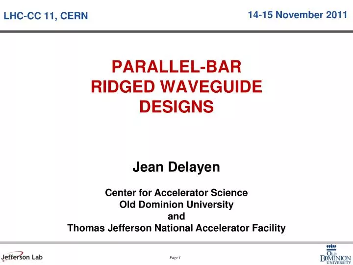
LHC-CC 11, CERN. 14-15 Nov ember 2011. PARALLEL-BAR RIDGED WAVEGUIDE DESIGNS. Acknowledgements. Subashini de Silva (ODU) HyeKyoung Park (JLab/ODU) Zenghai Li (SLAC) Lixin Ge (SLAC). Parallel Bar Cavity Activities at ODU/JLab. Deflecting Cavity

E N D
LHC-CC 11, CERN 14-15 November 2011 PARALLEL-BARRIDGED WAVEGUIDEDESIGNS
Acknowledgements • Subashini de Silva (ODU) • HyeKyoung Park (JLab/ODU) • Zenghai Li (SLAC) • LixinGe (SLAC)
Parallel Bar Cavity Activities at ODU/JLab • Deflecting Cavity • Jefferson Lab 12 GeV Upgrade (499 MHz) (DOE-NP, ODU-Niowave P1 STTR completed) • Project-X(365.6 MHz) (ODU-Niowave P1 STTR completed) • Crab Cavity • LHC Luminosity Upgrade (400 MHz) (LARP, ODU-Niowave P2 STTR) • Electron-ion Collider (750 MHz) (ODU-Niowave P1 STTR completed, P2 funded)
Parallel-bar Cavity Properties • Compact design • Supports low frequencies • Fundamental deflecting/crabbing mode has the lowest frequency • No LOMs, no need for notch filter in HOM coupler • Nearest HOM widely separated ( ~ 1.5 fundamental) • Low surface fields and high shunt impedance • Good balance between peak surface electric and magnetic field • Criteria: Ep<35 MV/m, Bp<80 mT
Parallel-bar (ODU) E field on mid plane (Along the beam line) B field on top plane
Ridged Waveguide (SLAC) 400 MHz LHC Crabbing System
Parallel-Bar / Ridged Waveguide 499 MHz JLab Upgrade Deflector Fabrication under way 400 MHz LHC Crabbing System Fabrication under way 750 MHz ELIC Crabbing System Final design underway 365 MHz Project X Deflector
Non-linearities 5 mm 10 mm 0 mm
Multipacting Simulations • Field level scan: • 0.045 MV – 5.5MV, interval 0.045 MV • Initial Particles distributed on all exterior surface • Each field level ran 50 RF cycles.
Model Mesh & Fields • Frequency:400.06686MHz • 690k tetrahedron mesh E Field magnitude B Field magnitude
Resonant Particles Distribution Peak SEY
Resonant Particles in Cavity • One point first order • Impact energy below the peak value, 400eV. • Large enhancement counter region: 0.6MV ~1.0MV Peak SEY Resonant Particles Distribution at all field levels SEY >1 Resonant Particles Distribution at 0.6MV
Resonant Particles in Coupler Region Deflecting Voltage vs. Impact Energy for resonant particles Deflecting Voltage vs. maximum enhancement counters for all particles in 50 RF cycles. • Two points (inner and outer conductors) first order • Impact energies are lower on inner conductor than those on outer conductor • Enhancement counter reached 10^4
Resonant Particles in Beam Port Region Deflecting Voltage vs. Impact Energy for resonant particles Deflecting Voltage vs. maximum enhancement counters for all particles in 50 RF cycles. • One Point First Order resonant particles • Peak enhancement happens between 0.65 MV and 0.85 MV
Resonant Particles in High B Field Region Deflecting Voltage vs. Impact Energy for resonant particles Deflecting Voltage. maximum enhancement counters for all particles in 50 RF cycles. • One Point First Order resonant particles. • Peak enhancement counters are between 3 MV ~ 4 MV • Peak value is around 50
Pressure Sensitivity • 1/8 model • Fixed support at the beam pipe ends • Varying external pressure up to 1 atm • The inside vacuum is deforming by the cavity deformation • The deformed vacuum is extracted and the frequency is solved by ANSYS high frequency eigen solver • The frequency is not 499 MHz before the deformation because the cavity is oversized anticipating the thermal shrink at 2-4K Pressure sensitivity -212 Hz/torr
Pressure Sensitivity Effect of surface’s deformation to the frequency shift One surface is artificially fixed (no deformation) at a time and the vacuum load is applied. Mechanical stability of the cap is most helpful to decrease the frequency change. The ‘Bar’ needs to be constrained against the pressure. The surfaces ‘slope’ and ‘OC’ seem to compensate each other. Constraining one against the other does not help. OC Cap Slope Bar F1: Frequency before the deformation F2: Frequency after the deformation
Some Numbers • Surface resistance of Nb at 400 MHz • 4.5K: 95 nΩ→105 nΩ • 2K: 1.3 nΩ→10 nΩ • Power Dissipation: • At 3 MV • Ep=32.5 MV/m • Bp=56 mT • P= 2.25W per cavity at 2K and 22.5W at 4.5K • At 5 MV • Ep=54.5 MV/m • Bp=93 mT • P= 6.25W per cavity at 2K and 62.5W at 4.5K
Next Steps • Test “proof of concept” cavity • Design of “beam line suitable” cavity and ancillary • Appropriate dimensions • Use genetic algorithm • Multipacting • Higher order mode couplers • Fundamental power coupler • Frequency tuners (coarse and fine) • LLRF and microphonics • Helium tank • Cryostat
Parting Words • ODU-SLAC collaboration in place and is fruitful • Multipacting analysis • HOM analysis • Coupler design • We are ready to design and develop next cavity • Need for a list of parameters and specifications