Download
1 / 16
160 likes | 284 Views
SEPS: The S MOS E nd- to-end P erformance S imulator. Universitat Politècnica de Catalunya, Barcelona, Spain. Objectives: Analyze instrument’s performance Develop geophysical parameters retrieval algorithms Generate data packets for L1 processor developpers Simulation tool:

E N D
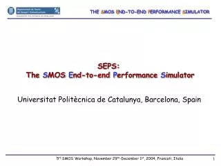
SEPS: The SMOSEnd-to-end PerformanceSimulator Universitat Politècnica de Catalunya, Barcelona, Spain
Objectives: • Analyze instrument’s performance • Develop geophysical parameters retrieval • algorithms • Generate data packets for L1 processor • developpers • Simulation tool: • Propagates SMOS orbit • Generates realistic TB maps from geophysical • Parameters • Computes instrument’s observables including • detailed error model with in-orbit temperature • dependence. • Applies error correction algorithms (internal • calibration) • Applies image reconstruction algorithm(s) • Projects reconstructed TB on the Earth • Antecedents: • MIRAS Simulator (1996), SEPS v1.0 (2001) ...
SIMULATOR BLOCK DIAGRAM & BASIC FEATURES Geophysical parameters Corrected Visibilities Processing simulator Measurement simulator Brightness temperature generator Image reconstruction and antenna-frame change to Earth reference frame Instrument modeling Calibration (error correction) Orbit calculator Correlations with noise injection,correlations (Vraw), and total power measurements Estimated TB input map(s) Simulated TB output map(s) Tv and Th maps with different incidence angle at each pixel Satellite position FOV Resolution Accuracy Sensitibity, etc. MIRAS/SMOS Figures of Merit Calculator
b1(t) H1(f) H2(f) b2(t) Nivel 0: SMOS observables= correlation products among all signal pairs collected by the array elements (“visibilities”) Complex Correlation Products Spatial coordinates Boltzmann constant Available Power Gain Receivers Noise Bandwidth y Physical Temperature of the receivers Antenna Radiation Volatage Pattern Brigthness Temperature Director Cosines x Antenna Solid Angle Obliqiuity factor (cos()) (u,v) = spatial frequencies where V(u,v) is sampled depend on array geometry and inter-element spacing (“d”) Ideal case: 2D Fourier transform Non-ideal case: includes antenna positioning errors, receiver frequency response differences
Cosmic, galactic Sun and Moon noise Up-welling atmospheric emission Ionosphere Scattered radiation Atmosphere Atmospheric down-welling emission Ground/sea Surface emission • BRIGHTNESS TEMPERATURE GENERATOR: • TH and Tv computed by the radiative transfer equation (models in bright.m) • Geophysical parameters from the CD set: • - "Global Data Sets for Land-Atmosphere Models ISLSCP Initiative 1: • 1987-1988 Vols 1-5” • - 1 resolution: 180 x 360 matrices (text file or.mat binary file) • land-sea mask at 1º/12 (ETOPO 5) + bilinear inter • - Monthly variation • - Parameters: . Atmosphere: liquid water, rain rate • . Land: land, snow & vegetation albedos, soil surface temperature, moisture & roughness, vegetation height, snow depth, • . Sea: surface salinity, temperature and wind speed, ice cover fract. • . Galactic noise map from Reich and Reich [1986]. • . Ionosphere: Intenational Reference Ionosphere '95 model & • International Geomagnetic Reference Field model Higher resolution maps can be used as input (developed in the frame of Synergy study)
Calibration Correlators Signal distribution network Antennas Receivers Level 1a: Calibrated Visibility Samples Error model • 1B/2L Digital correlators • I/Q down converter • Dual & full polarization • Noise injection calibration
Level 1b: Calibrated TB in antenna frame Spatial frequencies smapled by an Y-array Earth contour Spatial frequencies (u,v) Unit circle Earth “aliases” (u,v) principal domain Alias-Free Field Of View (AF-FOV) (u,v) hexagonal grid Inter-element spacing d= 0.875 Nyquist criterion : d/< • Nyquist criterion not satisfied: • Aliasing in TB images • 6 Earth aliases overlap Image reconstruction alg. includes redundant baselines, direct/reflected Sun cancellation (specular), sky imaging capability, “calibrated” fringe-washing funcs, blind correlations ...
Antenna ref. frame: X/Y-pol in (,) Earth ref. frame: H/V-pol in (lat-lon) x y TB images generated with SEPS
Higher levels: Calibrated TB in Earth ref. frame Faraday and geometric rotation corrections • Dual-pol mode (X/Y): • - all antennas at X-pol during 1.2 s, then at Y-pol • - SINGULARITIES in the transformation Txx, Tyy Thh, Tvv • Full-polarimetric mode: • - Combinations among X and Y polarizations in different arms during 2.4 s. • - NO SINGULARITIES in the transformation Txx, Tyy, Txy Thh, Tvv, but: • - LARGER NOISE Dual-pol. mode Full-pol mode
TB representation in cartographic projections Show multiple snap-shots with or without FOV: Projects the alias-freeFOV contour line for each snapshot Show snapshot #: projects a single snapshot of the simulation
SEPS Sample output Parameter Values vs. Snapshot • Pixel selection by right-clicking mouse on Earth surface point • Plot evolution of selected parameters and temperature results along the simulation • Disabling params. available for friendly evaluation
New features in SEPS 3.1 : • Since SEPS 3.0 a “light” option allows very fast computations • (~20 s/snap-shot at 1.2 GHz, 512 Mbytes of RAM) • Computation of Instrument Performances in terms of ESA SMOS SRD: • (user selectable) • - Radiometric Accuracy = sqrt (pixel bias ^2 + scene bias^2) • - Radiometric Sensibility (only due to thermal noise) • - Total Radiometric Error • Radiometric Accuracy computed directly: • SEPS also provides an estimate of bias, which can be (usually is) the error driver • Optimized for simulation time, • but requires the inversion of another data set of visibility samples slower • Projection of results on ISEA 4-9 grid • Short-circuit random number generator for internally generated instrument • and CAS parameters all parameters set at its nominal value SCENARIO SNAPSHOT RAD. SENSITIVITY V RAD. ACCURACY V RAD. BIAS V TOTAL RAD. ACCUR. V RAD. SENSITIVITY H RAD. ACCURACY H RAD. BIAS H TOTAL RAD. ACCUR. H ================ ========== ==================== ==================== ==================== ==================== ==================== ==================== ==================== ==================== test | 1 | 2.020117 | 5.261187 | -4.781066 | 5.635686 | 1.726082 | 3.532171 | -3.019847 | 3.931359 | test | 2 | 2.144572 | 5.283429 | -4.677936 | 5.702088 | 1.890499 | 2.767992 | -1.852858 | 3.351980 | test | 3 | 2.828202 | 5.946123 | -5.116489 | 6.584460 | 2.674459 | 5.746089 | 4.440021 | 6.338002 |
SAVING RESULTS IN A TEXT FILE: Name of the file DATA_ascii with the following format for iter=1:size(LAT,1), for i=1:size(LAT,2), fprintf(FID,'%6.0d %3.2f %3.2f %2.3f %2.3f %1.0d %1.0d %2.3f %3.3f %3.2f %2.3f %3.3f %3.2f %3.2f %3.2f %3.2f %3.2f %3.2f %3.2f %3.2f %3.2f %3.2f %3.2f %3.2f %3.2f %6.3f %3.3f\n‘, (iter-1)*size(LAT,2)+i,LAT(iter,i),LON(iter,i),PX(1,i),PY(1,i), OK(iter,i),fov4(1,i),TXant(iter,i),TYant(iter,i),TXrec(iter,i),TYrec(iter,i),THpix(iter,i),TVpix(iter,i), deltaTX(iter,i),deltaTY(iter,i),FROT(iter,i),ATT(iter,i),PSI(iter,i)); end end Can be read by other user applications for use in the development of geophysical parameters retrieval.
Auxiliary data OS map (1 overpass) Spatio-temporal averaging Multi-angular emission models SM map (1 overpass) Level 2: Concept of Multiangular Processing • TB corrections (atmosphere, reflected galactic noise ...) N 79 L1 processor L2 processor L3 processor
CONCLUSIONS • Accurate and complete end-to-end simulatorpresented: • Orbit generator, Brightness temperature generator, • Instrument modeling, Calibration, Image reconstruction, • Graphic Representation of single and multiple snap-shots, and • FOV properties calculator • Applied to: • study instrument’s performance, and • OS and SM retrieval algorithms. • Future work: • Update calibration strategy, add NIR calibration … • Include L2 processor.
WELCOME TO THE SEPS DEMO DURING POSTER SESSION