Download
1 / 26
260 likes | 366 Views
A detailed study integrating Computational Fluid Dynamics (CFD) & Particle Image Velocimetry (PIV) for benchmark turbulent flow analysis. Discusses equipment setup, methodologies, results, and comparison between CFD and PIV data.

E N D
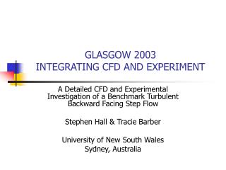
GLASGOW 2003INTEGRATING CFD AND EXPERIMENT A Detailed CFD and Experimental Investigation of a Benchmark Turbulent Backward Facing Step Flow Stephen Hall & Tracie Barber University of New South Wales Sydney, Australia
INTRODUCTION • Turbulent Backward Facing Step - benchmark flow • Compare Particle Image Velocimetry (PIV) and CFD • Not just to check CFD • Rather to use the best of each • What is the best of each? - first steps
TURBULENT BACKWARD FACING STEP • Mean flow structures • Characteristic lines and points • Wide velocity, turbulence range • Good CFD and PIV test
EXPERIMENTAL TEST RIG • Dimensions and PIV access
EXPERIMENTAL TEST RIG • Clear acrylic – light access • Low reflection base • Full side view
EXPERIMENTAL TEST RIG • High density PIV seeding – critical • Particle – hollow polymer spheres • Venturi jet seeder well upstream
HIGH RESOLUTION PIV • Basic 2D arrangement • Mean flow aligned in light sheet • Camera perpendicular to light sheet
HIGH RESOLUTION PIV • Constant intensity light sheet • Adjustable width and thickness
PIV VERIFICATION USING CFD • Contours From Standard PIV Images of Okamoto and Watanabe (1999) • Contours From a PIV Analysis of the Standard PIV Images
PURPOSE OF CFD • Not only to validate CFD against experiment • But to reveal greater detail about phenomena • And supplement experimental results • Make full use of the reliability of modern CFD
CFD APPROACH • 2D RANS finite volume (Fluent) • RNG k-, RSM turbulence closure (literature) • Second order interpolation • Ambient and boundary conditions – use experimental
CFD VERIFICATION ASSESSMENT • Key functionals Xr, Xs, Ys, Sp, Ss, Lift, Drag • Grid convergence – literature 200 cells vertical • Iterative convergence • 3D vs 2D – same grid resolution • 3% on Xr • Turbulence modeling, is code correct? • commercial code
CFD AND PIV COMPARISON • Many quality CFD and Experimental data sets • Most missing complete boundary conditions • not previously required • Perform both CFD and PIV myself • “exactly equivalent” • Work in raw variables u, v, Vmag • less need to non-dimensionalise • Contours – variation • Streamlines - direction
MEAN VELOCITY MAGNITUDE • Velocity Mag. in CS Plane, (top) PIV, (mid.) RNG k-, (bot.) RSM
STREAMLINES • Streamlines in CS Plane, (top) PIV, (mid.) RNG k-, (bot.) RSM
U HORIZONTAL VELOCITY • Mean Horizontal Velocity in CS Plane, (top) PIV, (mid.) RNG k-, (bot.) RSM
V VERTICAL VELOCITY • Mean Vertical Velocity in CS Plane, (top) PIV, (mid.) RNG k-, (bot.) RSM
VORTICITY • Vorticity Mag. in CS Plane, (top) PIV, (mid.) RNG k-, (bot.) RSM
VELOCITY MAGNITUDE AND STREAMLINES BEHIND STEP • Characteristic Lines in CS Plane, (top) PIV, (mid.) RNG k-, (bot.) RSM
FOCUSED BEHIND STEP • Mean Velocities in CS Plane, (left) PIV, (right) RSM tp=70 s
FOCUSED BEHIND STEP • Streamlines in CS Plane, (left) PIV, (right) RSM, tp=70 s
CONCLUSIONS • CFD and PIV reveal detailed flow structure • “Exactly Equivalent” simultaneous CFD and PIV • Highlights limitations in each • Improves confidence in results • Essential complimentary techniques
FUTURE DIRECTIONS • CFD should be first part of any PIV? • Unsteady 3D CFD PIV (TR PIV, stereoscopic) • Total integration of CFD PIV • PIV modifies turbulence closure model throughout • CFD error checks PIV and fills in error regions • mathematically rigorous
HIGH RESOLUTION PIV • Basic sub-systems • Optimise performance of each